MUSICAL FEATURES
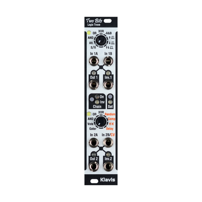
Two Bits is a dual logic processor with chaining and CV functionality.Each has two gate inputs and two logic sections with normal and inverted outputs, which can be used independently or chained together for more advanced processing.
The two sections provide a total of 2 general and specialized logic functions, and 15 if you include inverting resets (e.g., OR/NOR).Some functions provide real-time CV control for dynamic changes in state, and all time-related functions can be adjusted individually by the user and are automatically saved.Additionally, all outputs have LEDs that always indicate the actual status of the output.
HOW TO USE
Turn the knobs to select the logic you want to use for each section.When moving from one logic to another, the white LED turns off momentarily.By default, the white LED lights up when the knob matches the currently active function.This may not apply when changing settings.
Two Bits' two sections can be used independently or chained together internally for added versatility without the need for external patches.The available features can be divided into three categories as follows:

The "User setting" column contains user setting items, which can be set using the Set button.For settings, see "Edit settings" below.For details on each logic, please refer to "Logic/Function Algorithm Details" at the end.
chain of sections
The Chain button in the center of the module allows you to connect two sections.The chain function connects the output signal of section 2 as a third input, depending on the function of section 1, or as an output control that ANDs with the output of section 2:
When Function 2 does not have CV function
The Out 1 signal becomes Section 2's virtual third input.For example, selecting AND in section 3 provides a 2-input AND/NAND gate.

If Function 2 has CV function(Red labeling of Random, Comparator, etc.)
A virtual AND gate is created between the result of section 2 and its output jack.The results of section 2 depend on the results of section 1.For the output of section 2 to be 1, the result of both sections must be 1.Consider that section 1 validates the results of section 2.

Invert selects normal output or inverted output. The Set button is for adjusting ongoing settings (such as pulse duration) that exist for various functions.
Input/output
Inputs A and B can be used interchangeably and function the same way.However, if a CV related function (red label) is selected in section 2, input 2B becomes a bipolar CV control.All unpatched input jacks are virtually missing to avoid interfering with functionality.
Output 1 and Output 2 show the results of the currently selected function. Inv1 and 2 provide the opposite status of the associated main output jacks (Out 1, 2).Therefore, they represent the complementary logic of the currently selected option.
Edit settings
To edit user-editable settings provided by some features, briefly click the Set button.While the green Set LED is lit, you can edit a certain function by turning the knob in that section.Note that if features in both sections have editable settings, you can edit both during the same editing session.
The white LED indicates in which direction the current knob setting is by creating an upward tilt (turn to the right) or downward tilt (turn to the left) animation.Once the knob acquires the actual setting, the tilt stops, the white LED intensity reflects the setting, and the setting change is applied in real time.Once the settings are complete, press the Set button to finish editing.Setting changes are saved, preserving the current feature selection.
However, there can be a visual discrepancy between the active function and the knob's cursor display.Therefore, you must return the knob to its current function before selecting another function.Again, a white LED indicates the desired knob movement with a rising or falling animation.Once the knob is placed at the correct value, the animation will stop and the LED will become fully bright.
Displaying editable features
Features with user-editable settings are indicated by a normal blinking (or black blinking) Chain LED as follows:These LED displays do not affect the status of Chain/Inv settings.
- Chain LED yellow for section 1 function
- Section 2 features Chain LED blue (Inv)
Logic/functional algorithm details
Common functions of sections 1 and 2
OR:If any input is ON, outputs ON.
AND: Outputs ON only when all inputs are ON
XOR: Outputs ON only when exactly one of the inputs is ON
Features specific to Section 1
SR (Set/Reset)
This feature creates a toggle that is activated by two inputs.Input A is set, input B is reset. A rising edge on A sets the output. A rising edge on B clears the output.Adding pulses to the same input has no effect on the current state.
-A&B(minus A & B)
 "Minus A" refers to the inverse of A.This feature is useful when you want an And or Or when one of the input signals has the "wrong" polarity.This function can use normal or inverted outputs to serve as And and Or.
Using a regular output, this would be a two-input AND gate with an inverter on input A.

With an inverted output, this function can be seen as A OR –B, resulting in an OR gate with an inverter at input B.

Alternate
This is an edge-controlled logic function, and when we see an incoming rising edge on either input:
- The input signal is allowed to pass until its end (falling edge)
- Other inputs are ignored (disabled)
When the currently active input detects a falling edge on the enabled signal, it looks like this:
- Output goes low
- That input itself becomes invalid
- The other input is enabled (= you can now see the rising edge) and the roles of the two inputs are reversed
Note: If the input is already at level 1 before it becomes valid, the rising edge will not be detected and the signal will not pass.
Pulse on rise (up arrow), fall (down arrow), change (u/d arrows)
These three features are variations of the same feature.All of these create positive pulses that can be adjusted in length (each variation has its own duration setting).The only difference between each is what they respond to.

Another valid edge arriving while the output pulse is in progress will retrigger the timer and extend the current pulse.The pulse duration settings are arranged in two consecutive segments covering half of the knob range.
- Short: 1 to 20ms
- Long: from 21ms to 10 seconds
Section 2 specific features (no CV)
Gater (Gate merger)
Gater combines inputs just like the Or function, but retrigger the output whenever a new gate is started while the output is already active.The output signal reflects the duration of the input gate signal.
A user-adjustable setting determines the retrigger gap period.The available lengths are the same as the pulse function above.When used to bond gates, the gator gap is set as short as possible to minimize retrigger delay.The reason for extending the gap is that if the gap is too short, the module may not be retriggered.
With two active inputs:

If the third input is active in section 2 (x can be in any state):

In the table above, the naming of inputs A, B, and C is an abstraction of In 2A, In 2B, and virtual In 2C, which can be interchanged in any order.
Features specific to section 2 (with CV)
Input 2B becomes a CV input, so there is only one logic input (2A).
Random
If a rising edge is detected on the input 2A, the maximum chance of the signal passing is determined by a random percentage.
- Output stays low if not allowed
- If allowed, the signal passes completely until it terminates (= falling edge).
The random tolerance is user adjustable between 1% and 99%. CV allows you to change that setting in real time.
Delay line (DEL)
The input signal is delayed using the FIFO method (First in, First out).This means that the pulse train can be delayed with respect to individual timing and spacing.This feature is more than a basic "single pulse delay".
The delay settings on the knob are user adjustable and are arranged in two consecutive segments. One is a short setting (2 to 1 ms) and the other is 1 ms to 20 seconds.The sample rate is 1KHz, which means the resolution (accuracy) is 21ms.
Comparator
This feature provides an actual analog comparator. The two analog sources are input jack 2B and a user adjustable internal value.The voltage at input 2B is compared to a setting that covers the same span (+/-2V) as the input signal.If the input voltage is higher than the user setting, the output will be true.
When the input 2A is high, the comparison logic is inverted (output is true if the voltage is lower than the setting).If not connected, input 2A is considered zero.
Div/Mult
この機能により、通常の受信クロックを分周または乗算することができます。除算/乗算の比率はCVによって変更でき、合計 9つの異なる比率が利用可能です: /16、/8、/4、/2、x1、x2、x4、x8、x16
The default ratio is user adjustable and can be changed by CV. If CV is positive, the ratio changes to a faster output rate.For negative polarity, the rate will be slower.
Div/Mult range and timing
For ease of use, the output pulse and off-state cannot be shorter than 1 ms.