



RYK Modular Night Rider
¥65,900
(Tax excluded ¥59,909)
Quad resonator/filter bank with modulation sequencer
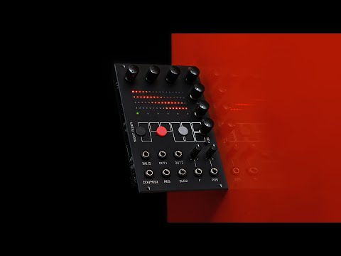
Night Rider is a 4-channel filterbank/resonator with modulation sequencer.
Combining 4 multi-mode filters that can control multiple parameters in an integrated manner with a 6-stage modulation sequencer creates sweeps reminiscent of 70's phaser filters, and reproduces vocal formant creaking and wheezing. , Carplus Strong, Filter Pinging, and many other effects in stereo.

Night Rider's four main filters are 4dB BPF [Pingable], 6dB BPF [Pingable], 12dB variable width BPF, Comb filter for Karplus Strong, and All Pass filter, depending on the filter type settings described below. (the functionality per filter is the same).combination in seriesALL PASS [APF]All modes except for are combined in parallel.
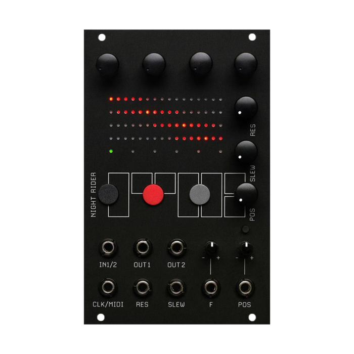
The per-filter parameters that can be adjusted are frequency, volume and stereo position.The top row of the display is indicated by Filter 1, followed by Filter 2, and so on with red LEDs across the display.Depending on the parameter being edited, the display of these red LEDs will change.
Use the 4 encoder knobs on top of the module to adjust the frequency or level of the 4 filters.Clicking on any knob toggles between frequency adjustment and level adjustment.Triple-click any knob to adjust each filter's pan position within the stereo field, and click again to return to frequency/level adjustment. To control the frequencies of all four filters simultaneously,'Next ●Hold the ' button and turn one of the upper encoders, or turn the F CV attenuverter without patching.
FREQUENCYWhen editing:

LEVELWhen editing:
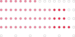
The 5 bright LEDs to the right of the Level bar indicate that the filter is entering the saturation clipping region.Set the level to a value lower than the 5 clipping LEDs for a clean sound without distortion.
PANWhen editing:

RES CONTROLor sending us a message onRES CV INPUTIf Resonance or Feedback is set to high values in , the signal can suddenly become louder as the filter matches the strong harmonics of the original signal.If this causes unintended saturation, lower the level of the filter.
Night Rider's modulation sequencer section consists of 1 stages of animation, one for each filter.Filter frequency, filter level and panning per stageYou can set the.
By animating the sequencer from one stage to another, the parameter changes from one value to another.SLEWHigher values create a glide in frequency changes, lower settings make frequency and level changes quicker.
At the bottom of the display, the row of six green LEDs indicates the current status of the modulation sequencer.stage positionindicatesThe sequencer stage position is set to ' Next ●' and ' Prev ' buttons, or an external clock orCLK/MIDI InputCan be moved by MIDI clock viaAlso, the stage positionPOSknob, orPOS InputYou can also move and interpolate with an external CV via
The maximum and minimum sequencer stage positions areSEQUENCE RANGECan be set in options.
If you use an external clock to trigger your sequencer (MIDI or analog),SEQUENCE CLOCK DIVISIONYou can use the settings to divide the timing.
To adjust the direction of movement of the sequencer,SEQUENCE MODETake advantage of options.
' PREV ● ' buttonBy pressing and holding for about 1 secondSTAGE EDIT MODEActivate (stage edit mode).Indicated by a single flashing green LED, this mode allows you to edit individual sequence stages even while the modulation sequencer is running.This mode exits after a few seconds of inactivity on the filter knob.
In setting mode, you can set the filter type and sequencer. By holding down 'PREV ●' and operating the upper encoder knob, you enter the setting mode, and the setting target is determined by which knob you operate.
Select the filter type you want to use.



Note that in the two All Pass Filter modes the filters are cascaded in series and the level control setting adjusts the overall level rather than the individual filters.Also, Out 2 and Out 1 output a mix of filtered signal and subtractive dry and additive dry, so no pan control is available.


This setting triggers stages in the modulation sequencerCLOCK INPUTsubdivide theFor example, setting it to ' 4 ' will trigger a sequencer advance every 4th clock pulse.This setting applies to MIDI and analog clock inputs.In addition,MIDI CLOCK INPUTis predivided by 6 before doing the clock division. [Because the MIDI clock is 24ppqn]


Sets the maximum/minimum length of the sequencer stage.Pressing the knob toggles between minimum and maximum settings.The minimum value is indicated by a left-pointing arrow, the maximum value by a right-pointing arrow, and the valid length is indicated by a solid green LED.


' Memory ● Hold the ' button and turn Knob 1 or Knob 2 to save and load filter bank and modulation sequence parametersPATCH STORAGE MODEStart.


KNOB 4 - LOAD FILTER PRESETS:
You can load predefined filter settings into the current stage.
13 vocal formants and 13 chords are available.Rotate the knob to select the preset number, press the knob to load the preset settings for the current stage.
| vocal formant [ prefix P ] | code [ prefix C ] |
|---|---|
| 1-ee | 1-Major |
| 2-i | 2-Minor |
| 3-ay | 3-Diminished |
| 4-e | 4-Augmented |
| 5-au | 5-Major 7th |
| 6-u | 6-Minor 7th |
| 7-a | 7-Dominant 7th |
| 8-aw | 8-Diminished 7th |
| 9-oo | 9-Augumented 7th |
| 10-ar | 10-Suspended 2nd |
| 11-er | 11-Suspended 4th |
| 12-ir | 12-Suspended 2nd |
| 13-iir | 13-Suspended 4th |
RYK Modular FirmwareYou can check the firmware release information on the page.
To update, first power up the module.There are two small switches on the back of the module, 'FIRMWARE' and 'RESET'.
While holding down the FIRMWARE button, click the RESET button and release the FIRMWARE button.
Connect the module and computer with a USB B micro cable.Make sure that the cable you use at this time is a high-quality cable that supports data transfer, not just power supply.Also, the cable connects directly to the computer without going through a hub.
A USB disk named 'RPI-RP2' will appear on your computer. Copy or drag the UF2 firmware file to the 'RIP-RP2' disk.If all goes well, the disk will automatically eject and the module will reboot with the new firmware.