
Skip
Summer sale has started! (Including sale items)SUM10Enter the code to get 10% off in stock(Some exclusions apply)
Free domestic shipping over 15,000 yen | FREE DHL SHIPPING WORLDWIDE FOR ORDERS 50K+ yen : Details
Summer sale has started! (Including sale items)SUM10Enter the code to get 10% off in stock(Some exclusions apply)
Free domestic shipping over 15,000 yen | FREE DHL SHIPPING WORLDWIDE FOR ORDERS 50K+ yen : Details

Instruo Lion

¥62,900 (Tax excluded ¥57,182)
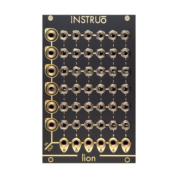
6x6 matrix mixer routed by pins using TRS plugs

Format: Eurorack
Width: 16HP
Depth: 27mm
Current: 30mA @ + 12V, 30mA @ -12V

Manual pdf (English)

* This product has many scratches on the panel for jacking.Please note on your purchase.

MUSICAL FEATURES

The Instruo Lion is a 1970x6 matrix mixer with a pin-style interface, reminiscent of the modular synthesizers of the 6s. From signal routing to effect insertion to accurate summing with stepped attenuation, it enables intuitive and quick live patching with the included pin cable or insertion cable, making it the center of the system's I / O network. I will carry it.

  • 6x6 pin style matrix mixer
  • Inserting send / return into the signal path
  • Accurate summing
  • Passive multiple ability
  • Gradual attenuation using channels 3-6
  • Includes 10 pin cables
  • Includes 2 insertion cables (black = send, gold = return)

HOW TO USE

The Lion interface is divided into three sections, and the signal circuits are designed with DC coupling for both input and output. On the left side of the module are six vertically arranged signal input terminals numbered 1 through 6, and at the bottom of the module are six horizontally arranged signal output terminals numbered α through ζ . Connecting these inputs and outputs are TRS sockets called patch points arranged in a matrix . In addition to signal routing and effect insertion functions, patch points also function as passive multiples. Input signals can be taken directly from patch points using standard mono patch cables.

  • α(Alpha) andβFrom (Beta), the combined signal is always output in unity gain.
  • γ(gamma),δ(delta),ε(Epsilon) andζFrom (Zeta), the mix of the pin-connected sources is output with unity gain, but if there is no patch on the output terminal to the left of the target, the output signal is added directly. This throughput produces 1/3 of the gain reduction. Also, the gain of the input signal is added by inserting multiple pin cables in the same line.
    For example, input a signal to input 1 and the first lineαIf you insert a pin cable intoαandβThe output from is unity gain. This time,γThe output signal from is attenuated to 1/3,δThe output is further attenuated to 1/3. By adding the channel outputs in this way, stepwise attenuation is applied.

  • Similarly, input a signal to input 1 and the first lineζIf you insert a pin cable intoζThe output from is unity gain.この時、追加のピンケーブルを1行目のAt this time, add an additional pin cable to the first line.εBy inserting it in, the gain of the signal is increased by 2/3.続けて追加のピンケーブルを同行のContinue with an additional pin cableδWhen inserted in, the gain of the signal is further increased by 2/3.

PATCH patch

mixing:

  • Connect the signal you want to mix to one of the inputs andζMonitor the output.
  • Insert the pin cable in the corresponding line on the patch point.
  • Different attenuations are applied depending on where the pin cable is inserted.
  • Inserting multiple pin cables in the same line adds gain to the input signal.

For example, if you input a signal to input 1 and insert a pin cable into ζ on the first row , the signal will be output at unity gain. Each time you move the pin cable to the left socket on the same row, excluding the first two patch points where the same amount of attenuation is applied, the signal will be attenuated to 1/3.

Effect Inserts:

  • Input the audio signal to input 1 andαMonitor the output.
  • 1st lineαPatch the insertion cable to.
  • Connect the black (send) side of the insertion cable to the input of your favorite effect.
  • Connect the output of the effect to the gold (return) side of the insertion cable.
  • This method can be performed with any I / O.

Basic feedback:

  • Input a signal to input 1ζMonitor the output.
  • 6st lineζInsert the pin cable into.
  • With a patch cableαReturns the output to input 6.
  • 6st lineαPatch the insertion cable to.
  • Connect the black (send) side of the insertion cable to the VCA input.
  • Connect the output of the VCA to the gold (return) side of the insertion cable.This establishes a VCA-controlled feedback loop.
  • The first line to introduce the audio signal into the loopαInsert the pin cable into.

DEMO


Top
x