MUSICAL FEATURES
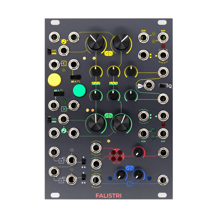
Frap Tools Falistri is a fully analog versatile movement manager designed for voltage generation and editing. Falistri is roughly divided into four sections, the section at the top of the panelTwo function generators, The bottom of the panel is a cascaded dualFrequency dividerとThrough limiter,andFour quadrant multiplier (ring modulator)Consists of.
HOW TO USE
The Falistri front panel is color coded by functional section.In addition, by labeling the signal input / output related to each parameter and the dotted line or solid line indicating the normalized signal path, the desired operation can be performed smoothly.
Interface
The explanation of each part is displayed by mouse over.If there is an internal connection to the jack, such as the input of each modulation bus, around the jackDotted line of the corresponding source colorIs labeled, and once you get used to it, you can easily grasp the routing.
Function generators
The two generators are designed to give you the functionality you need quickly and intuitively, and have many inputs and outputs.The slope shape control has the following features.Reference video link
-
Shape-independent duration --When shaping the envelope, you can freely morph the slope shape from logarithmic to linear or exponential while maintaining the time values of Rise and Fall.
-
The shape can be adjusted for each stage --Can be set to logarithmic Rise and logarithmic Fall, linear Rise and logarithmic Fall, or any other mode combination.This allows deep sound engraving, both as a control voltage and as an audio source.
Times
The time for each stage is set with the Rise and Fall knobs. The Rise knob sets the time it takes for the function to reach its maximum level, and the Fall knob sets the time it takes for the function to "rest" after the Rise stage (in Transient mode) or after Hold (in Hold mode). ..These parameters can be individually modulated on any CV using the corresponding jacks, andV / OctIt can also be modulated at the same time via input.This input works the opposite of the individual CV input.For perfect operation over different octaves, you can use it like a V / Oct converter by keeping both the Rise and Fall stages at equal values.Reference video link1, 2, 3
The Time Scale switch scales the Rise and Fall of each generator, the time coefficients of both stages.
Trigs and Modes
Two manual buttons and external trigger / gate input are available in three modes:
-
loop --Trigger the start of Rise at the end of the Fall stage.It does not require a trigger input, but if it does, it will trigger the Rise stage again. Suitable for use as an LFO or oscillator.
-
Transient --At the start of the Rise stage, the trigger / gate signalOnly transition from low to highIs used and the Fall stage is automatically triggered at the end of Rise.One-shot Rise-Fall function, orADIt can be used as an envelope.
-
Hold --The low-to-high transition of the gate signal is used to start the Rise stage, and the Fall stage is the gate signal.Transition from high to lowTriggered by.Hold the Hold stage when the gate signal is "high (1.5V or higher)" longer than the Rise stageAHRIt will be an envelope.The Fall stage is triggered when the gate is low.
Everything while the function is workingRetrigger signalRecalls the Rise stage of the function.Specifically, it works as follows
- If the function is already in the Rise stage, it will not be retriggered
- If the function is a Hold stage, it will not be retriggered
- If the function is the Fall stage, start Rise from the level at the time the trigger was received.
- If the function is the Rest stage, launch a new function
Falistri is a triangle core generator with a wave shaper stage applied after the core, causing retriggers during the Fall stage and some interesting discontinuities when using non-linear waveforms. Will occur.
Green Alternative Retrig (On Rest)
Green, the second generator provides a unique feature that can be enabled with a switch on the back of the module.
-
To rise(Upper position) -Same operation as the yellow generator
-
On Rest(Lower position) -Retrig is accepted only when the generator is in the Rest stage.
On Rest function makes the generatorFormant oscillatorCan be used like.This feature roughly maintains the spectral components of the designed function over several notes, and if this "slave" period is longer than the "master" period, frequency division of the external frequency used for the trigger (/2, / / 3, / 4, / n ...) is done.The Trig / Gate LED does not illuminate when the green generator is set to On Rest and the Play mode is set to Transient.To see if the generator is set to To Rise or On Rest, set the generator to Transient mode and press the Trig / Gate button. If the LED lights up, you can see that it is set to To Rise, and if it does not light up, it is set to On Rest.When operating in Quadrature mode, it will be in To Rise mode regardless of the switch position.Reference video link
outputs
Each generator has 2 gate outputs and 3 CV outputs, for a total of 5 types of outputs.
-
Bipolar CV output: ± 5V range. Suitable for use as an oscillator for LFOs and audio rates.
-
Unipolar CV output: 0 / + 10V.Suitable for general envelopes, etc.
-
CV output with Athenu barter: Adjustable to any polarity and amplitude from 0 to + 10V or 0 to -10V.Reference video link1, 2
-
EOR (End of Rise) Gate Output: Output the gate at the end of the Rise stage
-
EOF (End of Fall) Gate Output: Output the gate at the end of the Fall stage
quadrature
Enable Quadrature mode by setting the switch labeled "Q" to the right position. QuadratureConnect the stages of two generatorsBy doing so, it is a special function that generates more complicated functions, and you can think of it as a pair of envelopes in which the stages depend on each other.As an example:
- Cycle start → Yellow generator starts Rise
- Yellow Rise ends → Green starts Rise / Yellow is Hold
- Green Rise ends → Yellow starts Fall / Green is Hold
- Yellow Fall ends → Green starts Fall / Yellow goes to Rest
- Green Fall end → Cycle end
To run Quadrature, set the Q-switch to the right position and set the green generator to Hold mode.This will give you three different results based on the operating mode of the yellow generator.
Yellow in Loop: Loop type Quadrature that automatically restarts from the yellow Rise stage at the end of the green Fall

Yellow in Transient: Single Quadrature Cycle

Yellow in Hold: In a single Quadrature cycle, the yellow Hold stage depends on both the green Rise time and the impulse / gate length to trigger the yellow generator. Quadrature mode disables the green On Rest feature, as described in the On Rest section.
ADSR
When Quadrature is enabled, you can create envelopes such as ADSR and AHDSR by setting the relative level with Max output and Athenuverter.AttackIs controllable with the yellow Rise,HoldIf is required, define it with green Rise and yellow Hold (yellow = Hold mode).At the start of the yellow Fall, the green generator will be in Hold mode until the yellow envelope reaches the end point.The green Hold level is set with Athenu Barter.While the yellow Fall level is higher than the green Hold level, the envelope isDecayIt will be a stage.When the green Hold stage level is higher than the yellow Fall, the envelope willsustainEnter the stage and set the period with the yellow Fall time.When the yellow Fall finishes, the envelope is set with a green Fall timeReleaseStart the stage.Reference video link1, 2, 3, 4

Function Processors
Dual Cascaded Frequency Divider
Each of these processors, also known as flip-flops, or sub-octave processors, changes its logical state each time it detects a low-to-high transition.The upper and lower DCFD circuits are semi-normalized to obtain 2/1 and 2/1 outputs from a single input signal.By setting the output range selector switch to the upper position, a unipolar signal (4V / + 0V) is generated, and at the lower position, a bipolar signal (± 10V) is generated.When using an audio signal as inputSub octave generator(The carrier should be a square wave or a pulse wave).When a clock signal is inputClock dividerWorks like.When the trigger signal is input, the output is always the gate.This is because the flip-flop circuit keeps its state high or low until it detects a new rising edge input.You can also create interesting variable-width gate sequences using random clocks from SAPEL, etc.In the example below, a clock is used for the input, and 1/2 and 1/4 clock frequencies are acquired.

The following example takes a random clock as input.

The last example takes a rectangular wavy waveform as the audio rate input and outputs -1 and -2 octaves.

Reference video link1, 2
Four-quadrant multiplier
Four-Quadrant Multiplier (4QM) is a circuit that adds two signals to each other one by one. Similar to VCA, but the main difference is that you can freely combine positive and negative polarities by inputting bipolar signals to both inputs.this isRing modulator,Balanced modulator, ま た はThrough Zero VCAYou can also think of it as.It has excellent linearity and a bandwidth of 20KHz or more from DC, and the result of the operation depends greatly on the source used. Of the two 4QM input jacks, the upper input 2 is semi-normalized to the yellow generator's unipolar output and the lower input 1 is semi-normalized to the green unipolar output.This also allows you to use yellow as an envelope and green as an audio source without using a patch cable. The Level knob affects the overall output by setting the amount of the two signals.In addition, the four LED matrices show which quadrant is currently in use.Input 2 moves the LED vertically (minus at the bottom, plus at the top), and input 2 moves the LED horizontally (minus at the left, plus at the right).
Amplitude Modulation & Ring Modulation (2 vs 4 quadrant)
When one of the signals used is bipolar and the other is unipolar, the 4QM effectively acts like a linear VCA.This is the default behavior, which means that if the green generator is acting as an oscillator, the yellow generator will control the amplitude.This setting allows you to use Falistri as a simple yet hands-on synth voice.Reference video link
If you also set the yellow generator to audio rate, Falistri will use Amplitude Modulation (AM)let's start doing. AM is also known as unbalanced modulation.This is because one of the two signals is the positive electrode only and only two of the four quadrants of the virtual Cartesian plane are used.As a result of the amplitude modulation, a signal with a frequency called "sideband" is obtained while maintaining the carrier frequency.If both signals are pure sine waves, there will be two of these sidebands.That is, the sum and difference of the carrier and modulator frequencies, the amplitude of which depends on the amount of modulation, but does not exceed half the carrier amplitude.If the frequency of the modulator is higher than the frequency of the carrier and the difference is a negative frequency, you will hear the phase inverted.

If both signals are bipolar, Falistri performs a "balanced modulation" that uses all four quadrants (a combination of positive and negative polarities) called ring modulation (RM). The result of RM is very similar to AM, except that RM suppresses the carrier frequency and the sideband is the only audible output.In this case, its amplitude will be the same as the carrier's amplitude.Reference video link

The 4QM section of the front panel has a small trimmer.This is useful for setting a unipolar envelope that drops to zero and a zero level for use, reducing the DC offset that causes low-order attenuation.
Linear Slew Limiter
Linear Slew Limiter when using quantized CVPortamentoor sending us a message onGlideAlso known as.This section smoothes all types of voltage transitions by independently controlling the rising and falling edges of the incoming signal.The left knob sets the rising voltage thru patched to the input, the right knob sets the falling voltage thru, and the result is sent to the output. The two LEDs help you check the operating status of the processor.