MUSICAL FEATURES
Batumi offers 4 channels of tempo-controlled oscillators that can each operate independently or in several synchronized modes. The wide voltage range of the 12 simultaneously available output waveforms, dependent on phase offset or variable ratio frequency, makes it a powerful and versatile multifaceted modulation hub.
Batumi implements anti-aliasing processing functions and highly adaptive analog filters on the output waveform, generating smooth signals even though it is a digital module. Significantly upgraded while maintaining the form factor and layout of its predecessor, it has been redesigned from the ground up using the latest components. It features V/Oct tracking, a new frequency multiplication mode, more waveforms including two types of random, and the operating range extends to audio rates.
HOW TO USE
Overview
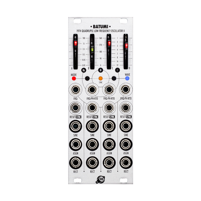
Batumi's four channels, arranged vertically from A to D, each have a slider with an LED and a row of input/output jacks. The leftmost slider controls the frequency of channel A. The remaining three sliders control four main parameters defined by the global mode settings: channel frequency (Hz), phase shift (ø), and frequency divide or multiply ratio (:).
There are three scales printed around each slider that identify specific parameter values depending on the mode of use. For example, in Free Mode, use these sliders to set the frequency of each channel in the range 3Hz to 0.01Hz (no external CV), and in Phase Mode, use the three sliders B, C, and D to set the frequency of each channel to 100°. Change the relative phase over a 3° range from The slider LED will flash according to the frequency and phase of the corresponding channel.
 Each channel of Batumi isYES,ASGN,andRECTGenerates three bipolar (±3V) waveforms available simultaneously through the jacks. Within each channel, the cycles of these three waveforms are strictly synchronized (fig. 5). However, depending on the mode of use, there may be frequency and phase differences between channels. Additionally, by using the Poti II expander, you can apply distortion and attenuation to each waveform. Note that an attenuator for square wave output is not provided.
Below each slider are two small buttons surrounded by three LEDs. leftFASHIONThe button is used to select the mode to use.FASHIONYou can check the selected mode by the color of the LED labeled. RightWAVEThe button isASGNSelect the output waveform that the jack generates,WAVE You can check the generated waveform by the color of the LED, such as triangular wave (red), descending sawtooth (yellow), ascending sawtooth (orange), trapezoid (green), stepped random (blue), and smooth random (turquoise). Masu. CentralSYNC The LED isRESET (LED off) andSYNC (LED lit) indicates settings for two types of synchronization methods (common to all channels). To switch between them, hold one button and click the other button.
The top two rows of jacks are dedicated inputs for each channel. They are labeled according to the features available depending on the mode you use.FRQ・PH・RTOThe jacks control the frequency, phase, or frequency ratio (divider or multiplier) of a channel with an external voltage. These jacks accept voltages ranging from -10V to +10V. Note that the values are added to the corresponding slider values, and in certain situations the voltage may reach the minimum or maximum values before reaching these limits.
4 つ のRESET/SYNCInputs allow each channel of Batumi to be synchronized to the phase or frequency and phase of an external signal. These inputs respond to rising edges, so gates and trigger signals provide the most accurate behavior.
action mode
Free Mode
In this mode, all four channels operate completely independently. To enter Free Mode,MODE LEDPress the MODE button multiple times until it lights red. The four sliders and CV inputs control the frequency of the corresponding channel. The operating range of each slider is 4Hz to 0.01Hz, but can be extended from 100μHz (9.76 hour duty cycle) to 28.4kHz by patching an external CV. This CV input provides V/Oct tracking, allowing the Batumi to function as four independent low-frequency modulation sources and four VCOs.
Additionally, in Free mode, random waveforms (both stepped and smooth) are generated completely independently with two samples per cycle (fig. 2). This allows you to take advantage of four uncorrelated sample-and-hold and linearly smoothed noise waveforms.


Phase Mode
Phase mode, indicated by a yellow LED, allows you to control the frequency of channel A in a similar way and over a similar range as Free mode. All remaining channels will follow the frequency of channel A, but their waveforms will be out of phase (fig. 4). The phase shift [ø] (or delay relative to cycle length) for channel A is controlled in the range of 0° to 360° using each slider. As the slider passes through phase shift values of 90°, 180°, and 270°MODE LEDflashes momentarily. By utilizing the corresponding CV input, you can add modulation with a depth of ±5 cycles.
Channels B, C, and DRESET/SYNCReset each phase by sending an impulse to the input (only if RESET is selected as the synchronization method). After a reset is performed, the slider position no longer represents the absolute value of the phase difference, but instead defines a new phase offset that shifts the entire waveform in cycles, and this new shift is applied to the slider and CV inputs. will be added to. Note that the offset will be canceled if the operation mode is changed.
Continuous phase modulation of a waveform using a signal connected to the CV input causes an instantaneous change in frequency and, therefore, rapid deformation of the shape (a fundamental principle of FM synthesis). This allows this mode to offer a wide range of waveforms that far expands the initial selection, and when operating at audio rates you can get classic FM sounds. Note that in Phase mode, the random waveforms are not independent, but are copies of the random sequence on Channel A with an appropriate delay (or inverse delay if the phase is negative). Combining this with deep phase modulation produces a sequence of four CVs with variable temporal relationships within a wide range of shifts, which can be used like a fugue machine.
Divide Mode
In this mode, the blueMODE LEDIt is indicated by . Channel A frequency can be controlled in the same way as Free Mode. The remaining channel frequencies can be set by subdividing the channel A frequency by an integer (fig. 5). The available division factors [:] are 1 (no division), 2, 3, 4, 5, 8, 16, and 32, which can be set with sliders, as well as the voltage patched to each channel's CV input. You can also modulate it with In other words, each waveform is slowed down by an integer number of times, and the corresponding cycle is lengthened by these multiples. Note that changing the ratio may cause the waveform to become discontinuous. The MODE LED flashes momentarily at the timing of changes between division coefficient values. Also, by using frequency division, it is possible to obtain a cycle that is even slower than the minimum value that can be set with the front panel and external voltage. If the factor is set to 32, the longest cycle obtainable is 53.3 minutes without external CV and 10 days with -37.9V CV.


Once in this mode, all channels operate synchronously in that they start at the same zero phase point and rejoin at this point after a few cycles. However, the phase relationship of the channels isRESET/SYNCIt may be modified by supplying an impulse to the input.
Synchronizing or resetting the phase of channel A restarts the cycle at the specified moment, followed by channels B, C, and D. Individual resets for channels B, C, and D affect only that channel. In this way, it is possible to obtain any combination of waveforms with a constant frequency and phase relationship that strictly follows the tempo of channel A. In Divide mode, like in Phase mode, the random waveforms are not independent, and a copy of the random sequence in Channel A is appropriately downsampled by the division factor. For example, if the ratio is set to 5 on channels B, C, or D, a new sample is taken from channel A for every 5 consecutive random values. However, even if all are set to the same divide value, resetting the phase (as mentioned above) can also shift the three channels, causing the values to occur at different times on different channels. There is a possibility.
Mult Mode
This mode is indicated by a blue-green LED. Channel A frequency can be controlled in the same way as Free Mode. The remaining channel frequencies can be set as the channel A frequency multiplied by an integer (fig. 6). In other words, for every cycle of channel A, there are multiple waveform cycles in channels B, C, and D. Available multiplication factors (ratios) are 1 (no multiplication), 1, 2, 3, 4, 5, 8, and 16, which can be set with sliders or patched to each channel's CV input. It can also be modulated by voltage. The MODE LED flashes momentarily at the timing of changes between multiplication coefficient values.
After entering this mode, all channels operate synchronously, starting at the same point of zero phase and merging again at the same point after each cycle of channel A. Changing the proportions precisely at this point avoids unavoidable discontinuities.
Note that the frequency of each channel cannot exceed 5.0kHz, so if the frequency multiplication result of channel A is greater than this, the coefficient is automatically reduced to the nearest frequency value below 5kHz. For example, if the multiplication result of 8 exceeds 5khz, the multiplication factor will be reduced to x5 and further if necessary.
The phase relationship of the channels isRESET/SYNCYou can change it by sending an impulse to . Synchronizing or resetting the phase of channel A restarts the cycle from the beginning and the remaining channels follow. Resetting to channels B, C, and D affects only that particular channel independently. Note that the speed at which channels B, C, and D are reset is limited by the algorithm's ability to calculate and maintain phase relationships. It can also handle audio rate synchronization combined with frequency multiplication, but you should not expect results as good as with analog oscillators. In this mode, the random waveforms are still not independent, and the sequence of channels B, C, and D is up-sampled by a factor defined by the slider and CV. In other words, they share the same values as the sequence from channel A. For example, if the ratio is set to 3 in channels B, C, and D, the third value in each will be the same as the corresponding value in channel A. However, even if these values are all set to the same multiplication value,RESET/SYNCcan be used to shift the phase of the channel, so it may occur at different times.
Sync and Tempo Control
Batumi can synchronize and follow the tempo of an external clock source in a variety of ways. Each channel isRESET/SYNCIncludes a cable-detection jack labeled . There are two synchronization methods that define how the receiving channel reacts to incoming signals. To switch between these methods, use the two buttons on the front panel.

RESET(LED off) resets the waveform to the initial point of the cycle (ø = 0) on the incoming impulse. Note that even if multiple consecutive impulses are input, they will not affect the frequency of the channel in the long run, since each only shortens one waveform cycle. However, if a periodic signal is used for reset, the effective frequency will change. The resulting waveform can be distorted in special ways. Each cycle is shortened or once every few cycles (fig. 1).
SYNC(LED yellow illuminated) adaptively tracks the input signal and adjusts the period of a particular channel to match the time interval between the two most recent impulses. Note that a continuous clock signal is not required to maintain the tempo. If an external clock is supplied, Batumi will follow all its variations. Note that the time scale of the waveform must be readjusted each time the clock frequency changes, so the shape will be slightly distorted at that point. Also, synchronization with an external tempo is possible on all channels in Free Mode, but only on channel A in other modes.
After synchronization, continuous frequency control via the corresponding sliders and CV inputs is no longer available, and can instead be used to select independent frequency division factors, similar to Divide Mode. In other words, the effective cycle length of a synchronization channel can be equal to one or several periods of an external signal (such as a master clock).
RESET/SYNCUnplugging the cable from the jack will return to continuous control.