MUSICAL FEATURES
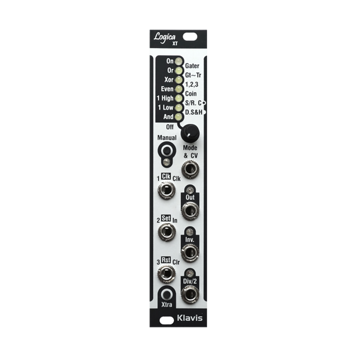
Klavis Logica XT is a voltage-controllable logic/gate processor. It has 6 types of basic logic functions and 8 types of more advanced logic calculation functions, and can accept a total of 3 signals (1 jacks and 4 button) as inputs. The output can use inverted signals such as AND and NAND at the same time, and also has a dedicated 1/2 divide output.
HOW TO USE
Logica XT performs logic operations using up to three input signals and pushbuttons.The functions of this unit are divided into the following two categories.
- Simple logic operations labeled on the left side of the panel, indicated by a single illuminated LED
- Advanced logic operations labeled on the right side of the panel, indicated by a pair of illuminated LEDs
Click the Xtra button to toggle between these features. You can select the function of the active column by operating the knob. For some features, you can edit the relevant settings by long-pressing the Xtra button and the changes you make will be saved automatically.
input jack
-
CV control input: CV input for mode selection. CV inputs are not available for advanced logic functions.
-
Input 1, 2, 3: For basic logic functionality, all of these inputs work the same, and you can put any signal into any jack.These jacks also have specific roles in some advanced logic functions.
Simple logic assigns unused jacks a natural initial value.
output jack
-
Main Output (Out): Provides the result of the logic operation of the selected function
-
Inverted Output (Inv): Outputs the inverted signal of the main output
-
Division by two outputs (Div/2): This output changes its state each time the main output changes from Off to On, providing a signal that is the main output divided by two (a flip-flop).It can be used for clocking external modules or for creating sub-octaves when working with audio signals.
ORing of outputs: to the output of the machine without additional modules for processing.It is also possible to apply an OR operation using passive multiples or stacked cables.
Control
-
Mode knob: Select one of the logic functions/modes for the active column.
-
Manual input button: This button acts like a fourth input.The initial state of the button depends on the selected logic function.The initial state can be changed by the user if necessary.
-
Xtra button: This button has two roles. The first one, as mentioned above, switches the column of logic functions to be selected by clicking. The second one edits the settings within the selected function and can be done by long-pressing the button. While editing, CV is disabled, and for basic logic, press the Xtra button and click the Manual button to switch the initial state. The result will be reflected on the Manual LED. For some advanced logic functions, you can adjust the time settings by holding Xtra and operating the knobs. Release the Xtra button when you are finished editing. Changes are saved automatically.
simple logic functions
These functions, also known as ``combinatorial logic'' or ``Boolean logic,'' are listed on the left side of the panel and indicated by a single white LED.
-
Forced On & Off states: Force output On or Off. The On state is indicated by a dedicated LED at the top of the column, and Off is indicated by all LEDs in the column turning off.In the forced state, the input jack is disabled, but only the manual button is available to invert the output.
-
And & Nand: The main output is turned on when all inputs and buttons are turned on.The manual button is On by default. And is a logic equivalent to a VCA, and in order to pass one of the connected signals, the other must be on.
-
Or & Nor: The main output turns on when at least one input or button is on. Or is the logic equivalent to a mixer, and the output will be on when any of the input jacks is on.The manual button is Off by default.
-
Xor & Xnor: This logic function works similarly to Or, except that the main output is Off when all enabled input jacks are On. Logica XT implements a special 2-input Xor that has a different result than concatenating a pair of 3-input Xor gates.Also, unlike other simple logic modes, the buttons do not have the same function as input jacks.Send to the cascaded Xor function by pressing a button.

Using two oscillators and two inputs, Xor can be used like the "digital ring modulator" that was implemented in the ARP Odyssey and KORG MS-2.

The manual button will invert the final result.
-
Even & Odd: The main output is turned on when the manual button and even-numbered input jacks are turned on.Inverted output works similarly for odd numbered inputs.The button is Off by default.
-
1 High: The main output will turn on when only one of the inputs, including the manual button, is on.The button defaults to Off.This feature can complement the rhythm pattern generator by providing a fourth sound gate if only one of the other three sound gates is active at a given step.
-
1 Low: The main output will turn on when only one of the inputs, including the manual button, is off.The button is On by default.
Advanced logic features
Also known as "sequential logic" or "state-based logic," these functions may have outputs that depend on a sequence of operations or have time-related effects.Unlike the simple logic function, input normalization is not required and is disabled, the Manual LED flashes while settings are being edited, the initial value of the manual button cannot be edited, and CV input is also disabled.
-
Gater: Gater combines all inputs like the Or function does, but retrigger the output whenever a new gate starts while one or more are already active.All inputs function equally, and the manual button introduces a fourth gate signal.The output signal reflects the time length of the incoming gate signal. By holding the Xtra button, you can set the length of the gap created for retriggering.Turning the knob will display LED off = 1 ms, then LEDs corresponding to values 4, 1, 2, 3, 4, 5, 6 ms will appear one by one, and further turns will display LEDs off for values of 7 ms to 8. A bar graph reflecting continuously variable values up to seconds is displayed.The initial value is 1 milliseconds.To maintain tight timing, it is recommended to set the value as short as possible for the target module.Longer gap time lengths are also available for more creative purposes.
-
Gt~Tr - Gate to Trigger & Trigger to Gate: Converts a gate or trigger to any input into a trigger/gate pulse of adjustable length.All inputs work the same way.The manual button introduces a fourth trigger/gate signal and all signals are combined and output (ORed).Turning the knob will display LED off = 4 ms, then LEDs corresponding to values 1, 2, 3, 4, 5, 6, 7 ms will appear one by one, and further turns will display 8 ms to 1 A bar graph reflecting continuously variable values up to seconds is displayed.The initial value is 10ms, which is suitable for typical Gate to Trigger conversions.You can also use longer triggers to create punchier envelopes.Regardless of the length of the input signal, Trigger to Gate can be achieved with a longer time length.
-
1, 2, 3 - Sequence Validation: This is a function where input numbering is important. The output will only turn on after the three input jacks see a trigger or gate in the proper order from input 3 to input 1.If the sequence is interrupted (e.g. input 3 becomes active immediately after input 1), the validation is reset and starts over.After the output is successfully turned on, if any further signal is input, the output will be turned off. (If that signal arrives at input 3, a new sequence may be restarted).If signals to different inputs overlap, only their rising edges are considered.The manual button inverts the state of the current output.
-
Corner: This feature provides three coin toss random generators with varying odds of winning depending on the inputs you use.If you win, the output will turn on for the duration of the input signal. If two or more inputs are used, the winning signal is combined (ORed).The winning probability for each input is 3/2 for input 1, 2/4 for input 1, and 3/8 for input 1.If the same input signal is input to two or more jacks, odds values will be added as shown below.

The manual button creates an ON that is mixed (ORed) to the state of the current output.
-
Set/Reset + Clock - S/R+C: The function of each input is indicated by a black box (Clock, Set, Reset) above the jack.This function implements a typical flip-flop circuit.The simplest way to use it is to input an arbitrary periodic signal to the Clock input to obtain 1/2 the signal from the main output. The Set and Reset inputs force and clear the output, respectively. A pulse to Clock inverts the current result.The manual button is an additional clock option.Without clocking, you can use just Set and Reset to get an S/R latch that holds the result static until the other input goes high.Only rising edges of the incoming signal are considered.For audio use, Logica XT implements an internally wired divider on the Div/2 output, allowing you to obtain 1/4 results.By inputting an oscillator to this function, it is possible to simultaneously obtain audio signals in the sub-octave and two octaves below.
-
Digital Sample & Hold - DS&H: A versatile feature consisting of sample and hold and an optional gate shaper, with Clock, In, and Clear labeled to the right of the input jack.There are two modes of operation depending on the knob position: the first half is a pattern delay, and the second half is a versatile sample and hold with delay. The first mode, Pattern Delay, is useful for creating rhythmic patterns with a delay function. Send a regular trigger/gate to the Clock input and a gate pattern to the Data input.The output isProvides a delayed copy of the gate pattern shaped by the phase and time length of the trigger/gate signal.

By holding down the Xtra button and operating the knob, you can set how many steps the pattern will be delayed by.As you turn the knob in the left half of its operating range, a row of LEDs will indicate the delay as follows: With LED off=1, the input will be copied to the output on the next clock.Then the LEDs corresponding to steps 2, 3, 4, 5, 6, 7, 8, 12, and 16 will light up.Next are LED pairs with 24, 32, 48, 64, 96, and 128 delay steps.Sampling works the same way if Data is slightly earlier/later than Clock rising.The endpoint of Data is not important because the output signal is shaped as a clock. The second mode, Digital Delay Line, allows the digital signal to be arbitrarily delayed up to 2 steps at any clock speed.Unlike the previous modes, there is no reshaping of the output signal with reference to the clock shape. If there is no signal on the Clock input, the module will generate its own 5000kHz clock internally.This gives you up to 1 seconds of delay adjustable with 1ms precision. By holding down the Xtra button and operating the right half of the knob, you can adjust the delay from 5ms to over 1ms, and the LED indicates the setting value with a bar graph display. Longer delays can also be obtained by using clocks of 5000 ms or less. It is also possible to patch the Inv output to the Datad input to create a clock generator with adjustable speed.A tip for audio use: the clock is modulated and you can use an audio mixer to get typical double-tracking unison and flanger effects.Only square wave or pulsed audio signals are valid.Also, the clock should run at several times the audio rate for proper sampling.
Simple logic overview
"Input" in this table also includes manual buttons, except for Xor/Xnor.

Advanced logic overview

Inv output is the exact opposite of Out. Div/2 output changes state as Out changes from Low to High.