Skip
Free domestic shipping over 15,000 yen | FREE DHL SHIPPING WORLDWIDE FOR ORDERS 50K+ yen : Details

Intellijel Designs Plog

End of production
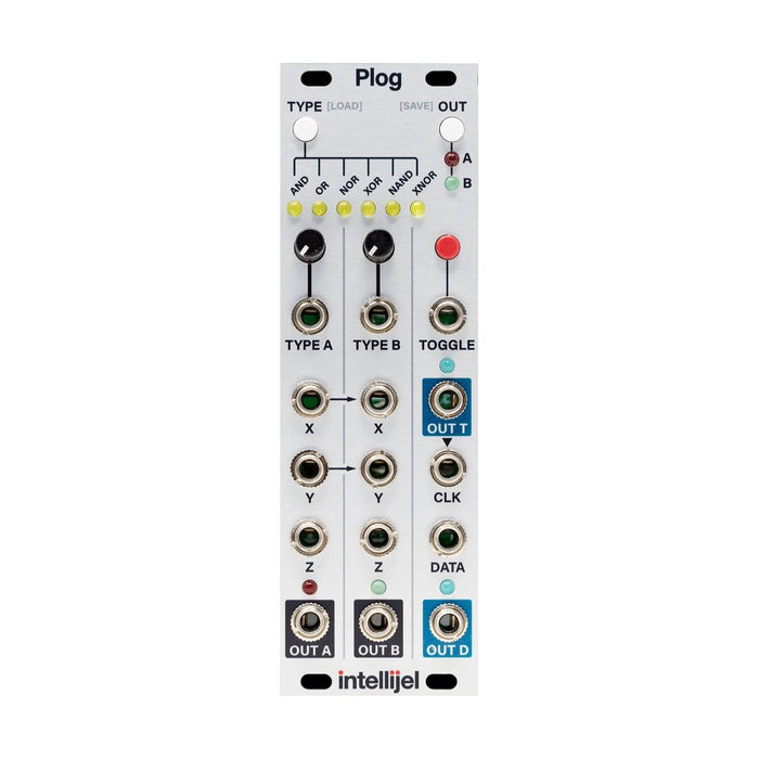
Voltage controllable logic module

Format: Eurorack
Width: 8HP
Depth: 29mm
Current: 55mA @ + 12V, 11mA @ -12V

For the latest Intellijel manuals and firmwareManufacturer support pageSee also

MUSICAL FEATURES

Plog has two programmableLogic sectionAnd T type (toggle)flip flop,D-type (data) flip-flop blockA highly functional logic module for music with It is also characterized by some ingenious internal connections between the sections. By inputting a gate signal and controlling the voltage of the logic type, you can create a fairly complicated rhythm pattern, or you can use it for self-generator patches and sound synthesis. In the PLOG, ON (TRUE, 1) is represented by 5V and OFF (FALSE, 0) is represented by 0V.

The logic type can be set for each A and B block. Use the SELECT button to switch between Block A / B and the TYPE button to select the logic type. Indicates the logic selected by the LED. In addition, the logic type can be voltage controlled by CV in the range of -5V to 5V (the higher the voltage, the more right the LED selects the right logic). Other features are as follows.
  • There are two logic blocks with three inputs, X, Y and Z. Since the input Z is internally connected to the input Y and the input Y is internally connected to the input X, 3-input and 2-input logic operations can be performed.
  • The logic type can be selected for each block and the voltage can be controlled (with attenuator).
  • The input X and the input Y of the logic block A are internally connected to the input X / Y of the block B. The output of B is set by a jumper to be internally connected as an input of the toggle flip-flop (changeable by the jumper).
  • The T-type flip-flop has a push button to manually trigger the toggle state. If you press and hold the trigger button for 1 second, the trigger input will be disabled and the tap clock will become simple.
  • The output of the T-type flip-flop is internally connected to the clock input of the D-type flip-flop. The inverse (NOT) of the D-type flip-flop output is internally connected to the D-type flip-flop input. With these two internal connections, the D-type flip-flop section acts as a toggle by default, and when combined with the T-type flip-flop, it becomes a / 2 or / 2 clock divider.
  • Logic section settings can be loaded and saved by holding down the TYPE or SELECT button for 1 second.
  • The module also works at audio rates.
 
The explanation of each part is displayed by mouse over

Details

Details of the function of each section.

Logic Operation

Each logic operation (operation) means the following operation (extracted from Plog manual). Input 1 to X / Y / Z means gate ON, 0 means gate OFF. This operation allows you to take a simple, sparse gate sequence as input and create a complex pattern.


Flip Flop

The upper right part of Plog is a T-type flip-flop, and the lower right part is a D-type flip-flop. The output of T-type flip-flop switches HIGH / LOW every time the gate is turned on (latching). Because of this it behaves like a / 2 clock divider. With the D-type flip-flop, the output is turned on and off at the same time as the input is turned on each time the clock is turned on. Its output is held during the time when there is no clock. In the Plog D-type flip-flop, the output of the T-type flip-flop is connected to the clock input, and the reverse (NOT) of the output of the D-type flip-flop itself is internally connected to the input. With these two internal connections, the D-type flip-flop section acts as a toggle by default, and when combined with the T-type flip-flop, it becomes a / 2 or / 2 clock divider.
Top
x