MUSICAL FEATURES
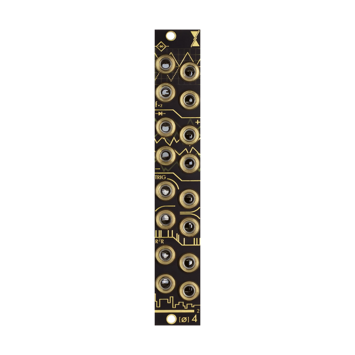
[ø] 4^2 isInstruo ochdThis is a unique and useful ochd-specific expander that can create 8 modulation signals by combining and processing the main unit's 16 LFO outputs.The module consists of the following four sections from top to bottom.
• 4 full wave rectifiers
• 2 pairs of analog Max/Min circuits
• 4 trigger sources that can be combined in a cascade fashion with normalization
• Four 4-bit DAC outputs to generate slow noise variations
Connection method

Connection status (Left: Ochd, Right: Ochd Expander (base color is different from the product version)).
Connect Ochd and expander with two 2-pin cables.The expander also requires power.On the expander side, the red stripe is on the bottom of both the power cable and the connection cable.
HOW TO USE
Full Wave Rectifiers - Full Wave Rectifiers
All the negative terminals of the four LFOs on the right side of the Ochd main unit are inverted, and each is output from the expander (4~0V).

Analog Diode Logic Circuits - Analog Max/Min Logic Pairs
Max/Min output outputs the larger and smaller voltage values of the two LFO channel outputs, respectively. Generates bipolar signals in the -2V to +5V range. The top two channels, the output labeled '+' (Max), outputs the highest voltage of the original LFO input pair at the time of the calculation. Conversely, the bottom two channels, the output labeled '-' (Min), outputs the lowest voltage of the original LFO input pair at the time of the calculation.

cascading trigger
 Generates an approximately 8ms trigger at the beginning of each LFO signal's rising edge. The four normalized outputs cascade clockwise to produce a mixed trigger signal when the previous output is unpatched.

R-2R 4-bit ladder DAC circuit
DA converts the combination of 4 LFOs on Ochd and outputs a stepped semi-random voltage. There are four combinations of four LFOs, each serving as an output. There are two factors that affect DAC output. First, the speed of each LFO sets the speed of each random signal. Second, the most significant bit (MSB) to least significant bit (LSB) order affects the size and speed of the voltage change. The cluster signal from ochd shown in the figure below generates four different random voltages (slow noise) from the expander.