MUSICAL FEATURES
Vector Wave is an FM & harmonic synthesizer with incredible power of 16 oscillator FM and working in vector synthesis or polyphony and multitimbral modes. Vector Wave's versatility allows it to be used as a standalone synth voice without the need for external modules such as VCAs, LFOs or envelopes.
- 4 banks x4=16 oscillatorsCan be used.FM within a bankcan be freely configured in series/parallel combinations.Realize complex FM and additive synthesis.
- In vector mode, a smallJoystickbetween banks of oscillators withMorphing.Record joystick movements as vectors and replay them with triggers or with external or internal modulation.自动化It is also possible to
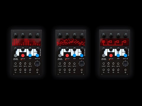
- Large pixel screen with excellent visibility and a retro feel
- Enhance the expressive power of FM synthesisWave warpingFunction allows continuous change of oscillator waveform from sine wave to triangle wave, sawtooth wave to pulse
- Widely change the soundwave folding
-
2 envelope generators(per voice in polyphonic mode) and2 LFOscan be assigned to any control
- Intuitive patchability from external and internal sourcesModulation slotcan be routed to any vector wave parameter
- the sound you createdinternal memoryYou can save up to 30
- Assigning Oscillator Banks3 voice modes: Monophonic Vector/Polyphonic Voice/Multi-Polyphony
- Supports polyphonyMIDI inputEquipped withVelocity, aftertouch and MIDI CC available as modulation sources
-
Additional V/OctExpander module with 3 x and XNUMX x Gate inputs available (sold separately)
HOW TO USE
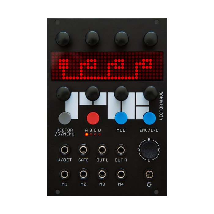
Overview
Vector Wave has 16 oscillators divided into fourbankdivided into four oscillators each.The 4 oscillators within these banks can be pitched by a factor of the fundamental frequency and combined in series or parallel to achieve complex FM and additive synthesis.
Each oscillator bank is used differently in the following four modes.Modes are selected with VECTOR/Q/MENU accessed by the gray button.
-
VECT 1/2: Creates monophonic voices from all four banks, with fourBank A, B, C, DControls the mix balance betweenThis vector of joystick positions can be recorded and automated or triggered via modulation sources, allowing you to create complex and repetitive changes to the timbre.These settings are accessed from the VECTOR/Q/MENU accessed by the gray button.
-
POLY: In this mode, settings from oscillator bank A are propagated to all other banks, creating a 4-voice polyphony.
-
MULT: In this mode 4 banks are individual sounds, individual voices, 4 voices are 4 CV/Gate pairs combined with expander modules, orIt is possible to play on four consecutive MIDI channels.

Various settings such as oscillator placement and harmonic structure, modulation assignments, modulator settings, various saves and model selections are explained below for each button you access.
[Red Button] Oscillator Bank
red buttonAccess the oscillator bank mode by pressing .A to D,Press the button repeatedly to switch between the four banks.
Each bank has 4 oscillators, each with 2 up and XNUMX knobs to control parameters.
The Oscillator screen display has four pages depending on the control being operated.The upper knob adjusts the frequency ratio of each oscillator.integer multipleto control (1-32) and push these knobs tofine tuneswitch to .
The lower knobs are for each oscillator.Levelcontrol the


FM algorithm• To activate a mode, click any knob in the lower row.In this mode, the oscillator can be selected between Carrier, Series Modulator and Parallel Modulator by pressing the knob.Modulation oscillators are shown as filled boxes, and carrier oscillators are shown as outlined boxes.The signal from the Modulation Oscillator to the Carrier Oscillator flows from left to right.
Modulation oscillators create rich, harmonically complex sounds by modulating the carrier.The amount of modulation applied is determined by the modulation oscillator level, the envelope 2 level, andQ Quick Performance Pageis controlled by the amount of XM[cross modulation] in
Example 1: Oscillators 1 and 2 are combined in parallel to modulate oscillator 3.

Example 2: Oscillator 1 modulates oscillators 2, 3 and 4 respectively.

Example 3: Oscillator 1 modulates Oscillator 2 and Oscillator 3 modulates Oscillator 4.
harmonic view
Activate the Harmonic View by pressing and holding any knob on the upper row.To exit from the display, press and hold the button in the same way.

This screen shows the harmonics of all four banks of oscillators in full screen.
Harmonic frequencies can be adjusted with the upper row of knobs, and amplitude levels can be adjusted with the lower row of knobs.Harmonics of the active oscillator bank are displayed brighter than others.
TIP: With Modulation SlotsBF(bandpass filter) orLFIf (low pass filters) are used, their effects can also be seen on this screen.
[Long press red button] Oscillator bank menu
the red oscillator buttonkeep pushingto launch the oscillator menu.To exit the menu, keep pressing the button as well.
This menu allows you to change the frequency relationship between the four VCOs in the oscillator bank.code, random cluster(each VCO's frequency changes to correspond to that setting).eachSaving, loading and copying bank settingscan run.

Use the lower left knob to select the function, and the lower right knob to select the desired bank to be affected.
CHRDIn mode, you can select a chord with the third knob on the bottom row. The base frequency of CHRD mode is determined by the first oscillator of the destination bank.If you select a chord here, the other oscillator pitches in the bank will change to the specified chord component sound.Since the chord setting is reflected, the numerical value of the frequency ratio of each oscillator is incomplete.
*The code here sets 1 VCOs in one bank. Assign one chord composition pitch to one of four banks, and use Poly mode or Mult mode to make chords in all four banks.
Also, the code is represented only by numbers, but the specific code name is as follows.
1-maj
2-min
3-dim
4-augs
5-dom7
6-maj7
7-min7
8-maj6
9-min6
10-maj7#5
11-maj7 b5
12-maj7 b3
13 - min7 #5
14 - dom7 sus4
LOADBとSAVEBThe operation withABCDAffects the current bank indicated by the bank LED on the
-
INIT: Reset all banks.
-
COPYTO: Copy the selected bank indicated by the ABCD bank LEDs to the target bank.
-
ALLES: Automatically assigns ascending harmonics to the desired bank.
-
ODD: Automatically assigns ascending odd harmonics to the desired bank.
-
RND: Automatically assigns random overtones to the desired bank.
-
CLUST: Automatically assign random overtone formant clusters to the desired bank.
-
CHRD: Automatically assigns one of 14 chords to the desired bank.
-
LOADB: Recall one oscillator bank from the saved number,ABCDload into the bank indicated by the bank LED on the
-
SAVEB: ABCDsaves the bank indicated by the bank LED on the .
[Blue Button] Envelope/LFO
Access the ENVELOPE&LFO mode by pressing the ENV/LFO button.the buttonpress repeatedlyThis will switch between ENV1 and ENV2, or LFO1 and LFO2, depending on which page is in use.
To select the envelope pageupper knoband to select the LFO pagelower knobIs used.
Envelope page
Two ADSR-type envelopes are available, ENV2 controlling the amplitude of the module's voice output and ENV1 controlling the amount of cross modulation applied to each oscillator bank.
The upper row of knobs control the Attack, Decay, Sustain and Release settings of the currently selected Envelope.

ENV2's default trigger source is the GATE input, but this can be changed to any other input.
To do so, click on any of the top row knobs and cycle through the trigger source options to Gate, M1, M2, M3, M4 or OFF.
If ENV2 is set to OFF, the output will be set to maximum.
LFO page
Two LFOs are available.These can be used, for example, to add movement to the sound by modulating attributes of the desired oscillator bank, such as amplitude.
Use the bottom row of knobs to choose between sine, triangle, saw, ramp, square, random, and noise waveforms, and adjust the LFO frequency.
Each LFO can be reset free or from one of the trigger sources Gate, M1, M2, M3, M4.Use the second bottom row knob to select these options.

[Blue Button] Modulation Slot
By pressing the Mod button,Modulation slotsto access.Press the button repeatedly to cycle through the slots.
Each slot configures a modulation source to modulate the desired attribute, for example Wave Fold in the oscillator bank.
modulation sourceincludes CVs from M1 to M4 inputs, or internal sources such as LFOs, joysticks and envelopes.
For example, oscillator bank A, etc.Destinationeach has a sub-option [suffix], e.g. WP [Wave Warp], to which these are modulatedtarget attribute.
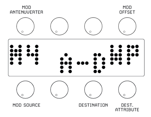
Use the bottom row of knobs to select the modulation source, destination and target attribute [suffix].
The upper row of knobs sets the amount of modulation applied (attenuverter), and the offset of the modulation.These can be set to positive or negative values.
For example, to create an inverted modulation (subtractive), adjust the Offset amount to a positive value and the Modulation amount to its negative equivalent.

In this example, ENV2 modulates the FD amount [Wave Fold] of oscillator banks A to D.
This envelope is used to subtractively reduce the amount of wavefolding as the envelope signal increases, and vice versa.
modulation source
-
M1, M2, M3, M4: External CV source from M1 to M4 jacks
-
JYX, JYY: Joystick X or Y position
-
EV1, EV2: Envelope 1 or 2
-
LF1, LF2: LFO1 or 2
-
CV: V/OCT pitch input
-
MVL: MIDI velocity
-
FOOD: MIDI aftertouch
-
MMD: MIDI modulation wheel
-
CC2-CC49: MIDI CCs
-
Gate**: GATE Trigger
-
M1[T]: M1 trigger input**
**These as destinationsVECAvailable as a trigger source only if is selected
Modulation destination
-
AD, or A,B,C,D: Each oscillator bank
-
A.M: Amplitude modulation
-
FM: Frequency modulation
-
XM: Oscillator cross modulation [amount of FM algorithm modulation]
-
WP: Waveform Warp [Sine Wave > Sawtooth > Continuously Variable Waveform to Pulse]
-
HM: Modulator Oscillator Harmonic Shift
-
DT: detune spread amount
-
PN: Bank output panning [-99 for 100% L output, +99 for 100% R output]
-
FDs: Wave folding [classical wave folding that produces complex overtones]
-
BF: harmonic bandpass filter
-
LF: harmonic low pass filter
-
VEC: Vector position animation from modulators or trigger playback from Gate or M1[T] inputs
-
LF1, LF2: LFO1 or 2 [AM: LFO amplitude modulation, FM: LFO frequency modulation, WV: LFO waveform selection]
-
EV1, EV2: Envelope 1 or 2 [A, D, S, R: modulate each segment of the envelope]
-
RST-YS/NO: Select and execute Erase All Modulation Slots
[Gray button] VECTOR/Q/MENU
Pressing the gray button repeatedly toggles between Vector/Q mode and the Setting menu.
In Vector/Q mode, use the upper row of knobs toQ Quick performance controlspage with the lower knobVectorSelect a page.
VECTOR PAGE [not available in polyphony or multitimbral mode]
the module isVECTORmode, use the joystick toA, B, C, DYou can continuously control the mix balance between banks of
The Vector page allows you to record joystick movements or positions and later replay or trigger them to automate timbre changes.
AvailableVECTORThere are two types of animation forVEC1records joystick movements over time,VECT2reproduces vector movements by memorizing the four vector positions of the joystick.
VEC1
Use the lower right knobs to set the speed of the vector being recorded and the trigger for playback.
The recorded joystick position is represented by the box in the center of the screen, and the reverse R on the left indicates the recording mode.

To record joystick vector motion, select any vector speed [20 or so is a good place to start] and start recording by pressing the lower left knob while operating the joystick.
To play the vector movement from the trigger source, use the modulation slot destination 'VEC' and select 'GATE' or 'M1T' as the trigger source.
This speed can be set with the knob on the bottom right of the VECTOR page.
Instead of triggering playback, you can also automate vector movement continuously over time from modulation sources such as LFOs or external CVs.
To do this, set the destination to 'VEC' in the modulation slot and select [except Gate/M1T] as the modulation source.
The VECTOR page speed value does not affect animation speed.If you want to control the joystick again, set the 'VEC' modulation source in the modulation slot to '--' to disable vector animation.
VEC2
A 4-part box 'CELL' on the screen represents the joystick's X and Y, 4 vector positions.
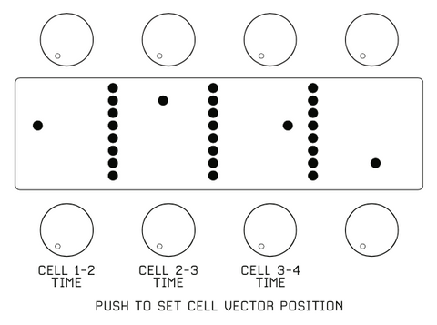
Move the joystick to any mix position and record the vector position by pressing one of the bottom row knobs.Repeat this operation for all four CELL boxes.
The 3 knobs on the left side of the lower row adjust the speed between each cell.For example, Knob 1 adjusts the time between Cell1 and Cell2, Knob 2 adjusts the time between Cell2 and Cell3.
Vector animation playback is represented by a vertical bar that scrolls across the screen.
To play back the vector movement from the trigger source, select the modulation slot destination'VEC'UseGATEor sending us a message onM1Tas the trigger source.
The speed between each cell is set with the three knobs at the bottom of the VECTOR page.
Instead of triggering playback, you can also automate vector movement continuously over time from modulation sources such as LFOs or external CVs.
To do so, in the modulation slot'VEC'as the destination, and select [except Gate/M1T] as the modulation source.
'Q' Quick Controls Performance Page
This menu provides quick access to some of the creative parameters of the oscillator bank, allowing you to set up convenient timbral controls for your sound.

-
XM: Oscillator cross modulation amount [0=no cross modulation, 99=maximum]
-
WP: Oscillator waveform warp amount [0=sine wave, 40=sawtooth wave, 99=pulse]
-
FDs: Oscillator waveform folding amount [0=no folding, 99=maximum]
-
DT: Controls the amount of oscillator detuning [distributes the tuning of each oscillator to create movement and depth]
*Q Performance Control affects all oscillator banks.To control individual banks, use the modulation slot destination offset controls.
Setting menu
In this menu, you can save and load each voice, select oscillator bank mode, tuning and MIDI settings.

Use the lower left knob to select the following setup menus.
-
LOAD: Load a voice from memory.Selecting a voice number with the lower RHS knob temporarily previews the voice.To load a voice, press the lower right knob.
-
SAVE: Save voices in memory.Select the voice number with the lower knob and press the knob to confirm the save operation.
-
FASHION: Placement mode for each oscillator bank.
-
VEC1: Monophonic voices using full banks, mixed by joystick or vector animation type 1
-
VEC2: Monophonic voices using full banks, mixed by joystick or vector animation type 2
-
POLY: Polyphonic mode that applies Bank A settings to 4 voices
-
MULT: Multi-timbral polyphonic mode [for Expander, or MIDI] that arranges each bank as an independent voice
When using MIDI in MULT mode, each voice is placed on consecutive MIDI channels.
For example, if the MIDI channel is set to 3, in MULT mode bank A will be ch3, bank B will be ch4..
*Vector synthesis is not available in POLY and MULT mode.
OUTPUT: Use the upper row of knobs to pan the outputs of banks A, B, C, and D.Panning can be reset to center by clicking the knob.
*If you are using only the left or right output of the module, you will get the best results if you set the output pan to only the jack you are using.
-
MIDI: Select MIDI OFF [OFF] or MIDI channel [1-12] for MIDI note and gate input.
*When MIDI is selected, V/Oct input and Gate input are disabled.
-
TUNE: Sets the master tuning in semitones [12=C3].
-
END: Sets master fine tune [±0-99].
connection jack
-
V/Oct: Pitch CV input [0-6V].
-
GATE: Gate input to trigger ENV1, ENV2.Also used to trigger vector animations.
-
OUT L - OUT R: Module's audio output pair.Panning settings for individual bank outputs are made from the Setting Menu.
-
M1-M4: These are modulation inputs that accept ±5V external signals and are used as modulation sources to modulate any aspect of the sound, such as cross modulation amount [XM] or waveform warp [WP] via the modulation slots.
-
M1[T]: Also used as a trigger source for vector animation playback.
-
M1-M4: Also used as trigger source for ENV2 or reset for LFO1/LFO2.
-
MIDI IN: This TRS MIDI input replaces the V/Oct and Gate inputs to control the pitch and gate of the Vector Wave.
To use MIDI and MIDI CC, select a MIDI channel in the Settings Menu.Back of modulehas a small switch for setting the TRS MIDI polarity from TYPE A/B [Default=B].
Also on the back of the module is a 10-pin header for connecting a Eurorack power supply and a 12-pin header for connecting a Vector Wave expander module.
If using an expander, connect the two with the included cable.
When connecting the power cable or the expander connection cable, make sure that the red stripe on the ribbon cable is aligned with the 'stripe' label on the board.