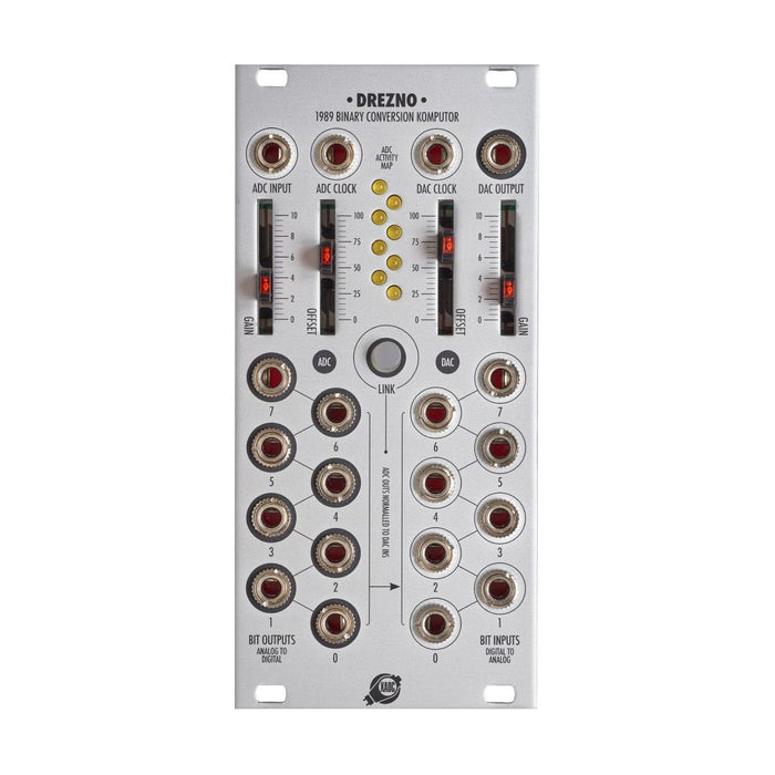
Drezno
- Analog to digital converter (ADC) which picks up the bit information that converted the input voltage into a digital value
- Digital-to-analog converter (DAC) which outputs the voltage to support from the bit information that I input
From is a conversion module making ends meet. I change a sound by inputting an audio system, and replacing bit crash and the bit and output a gate sequence by converting LFO and the random voltage into bit information, and various how to use is possible.
In addition, in Drezno, it is with interface of the signal conversion for Leibniz Binary Subsystem planned as a series of module series to perform 8 bits signal processing.
On the left side of Drezno, a voltage signal of the width of 10V is converted into binary (binary data) of 8 bits to 00000000,00000001,00000010, ..11111111 (analog --digital conversion, ADC). A bit of each " figure "is output as a gate by the output of the AD converter to 0-7 (a bit is 0 with 0V, 1 5V).
On the right side of Drezno, I express binary data of 8 bits by putting a gate in input to 0-7 and take it out as a voltage signal (digital --analog conversion, DAC).
In all ADC / DAC sides, the setting of GAIN and OFFSET has a very big influence on a signal after the conversion, too. I use an effect of the clipping positively and can twist a signal.
Eight gates which become the output of the ADC when I push the LINK button are input into the same DAC by internal connection. As a result, will output it after the output from DAC converted an input signal of the ADC into 8 bits data once; for the audio system
Bit reductionI bring about effect. In addition, it becomes the expander
LeipzigWith In the case of, Link mode, as for the output of the ADC, it is connected the inside to input of the DAC after it was handled in Lipsk.
ADC, the conversion in the DAC being carried out every interval for period of time, but deciding this
ClockADC and DAC have clock input separately, but work with an internal clock when they do not patch it. Because it is super-high-speed, and the internal clock works with 2MHz, I arrest a change exactly in the time for audio system and can avoid an alias noise. If I put square waves of oscillator --which is low speed in a clock
Sample rate reductionIn addition, when I input LFO and the voltage to change at random into ADC and put a clock in a grid of the rhythm and a timing to be, each output of the ADC is unique
Rhythm generatorAs functions.
* I cannot use the output when I used a high-speed internal clock for a gate triggering something. When want to output a normal gate sequence (is not an audio system rate), please use an outside clock by all means;).
In addition, the tips to make a patch of Drezno interesting have the following point. I may see favorite how to use while I try a lot of patches.
- I try to change GAIN, OFFSET.
- I perform modulation of quantity of input signal in VCA
- Even one tries to patch the output of the ADC wherever of the input of the DAC without doing LINK
- I combine it with a logic system module
- A bigger figure changes slowly when I input LFO in the ADC and I am busy with the small figure and change
- In the DAC, the bit of a bigger figure has a bigger influence on signal