* Except for the parts that have been changed, the following description is for firmware version 1s. There were many additional features in the firmware 2 series released in the spring of 2017. See "Firmware 2.0" below for an overview. For Shapeshifter purchased at However, please note that the preset will be deleted by the update. Please email us with your order number.
Overview
Intellijel Shapeshifter is a sophisticated and deep dual * digital * wavetable oscillator created in collaboration with Cylonix. By using a powerful FPGA board, from code generation to percussion, vocoder, and echoMany authentic synthesis optionsTo achieve.The signal is internally processed at a rate of 25Mhz and the effect of aliasing noise is very small and the sound quality is high.
Oscillators
The frequency of Osc1 is set by the Coarse and Fine knobs near the center, and the Pitch 2 input, and the frequency of Osc1 changes accordingly, but is also controlled by the Ratio knob, CV, and Pitch 1. The ratio can be set to a beautiful integer ratio with oscillator 2 by turning on the Quant button, so it is unlikely to be a dissonant tone when used as a modulator of linear FM as well as harmony. The Shape2 / 1 knob on the right controls the waveforms on various wavetables. Wave For the two VCOs, you can select their wavetables with the WAVE BANK button → Encoder. There are 128 wavetable banks, and each bank has 8 waveforms, and it is possible to move smoothly between them (512 samples). Once a bank is selected, the waveforms within that bank can be controlled by the Shape knob and the Shape CV to create various waveform movements. There are also a variety of other synthesis options, and the settings are accessible via various buttons. Settings can be saved to presets, and presets can be sequenced in a practical way (or sequenced chords) and morphed
It has the following characteristics. See "DETAILS" below for details of each option and detailed operation methods.
Preset sequence morphing
Thru Zero FM (About TZFM)Rubicon(Please see the description)
Delay-based resonator (can be used as a looper)
64-band vocoder
Selectable audio rate (AC couple) modulation MOD A can also modulate phase.
Analog wave folder (Analog wave folder uFold Can also be used for external signals.
There are various options such as oscillator sync, pulse output, combination processing, etc., which expands the range of synth sizes.
MOD B also offers a variety of selectable DC modulations. Press the button for the parameter you want to modulate twice. -Combo modes -Waveform TILT -Overdrive (in code mode) -Delay depth and FB -Decay time (percussion mode)
With 8 voice chords to be detuned, you can select from 64 chords, including just intonation and equal temperament.
In percussion mode, the signal from the oscillator is output through a VCA with a built-in envelope. Decay modulation and AR mode operation are also possible.
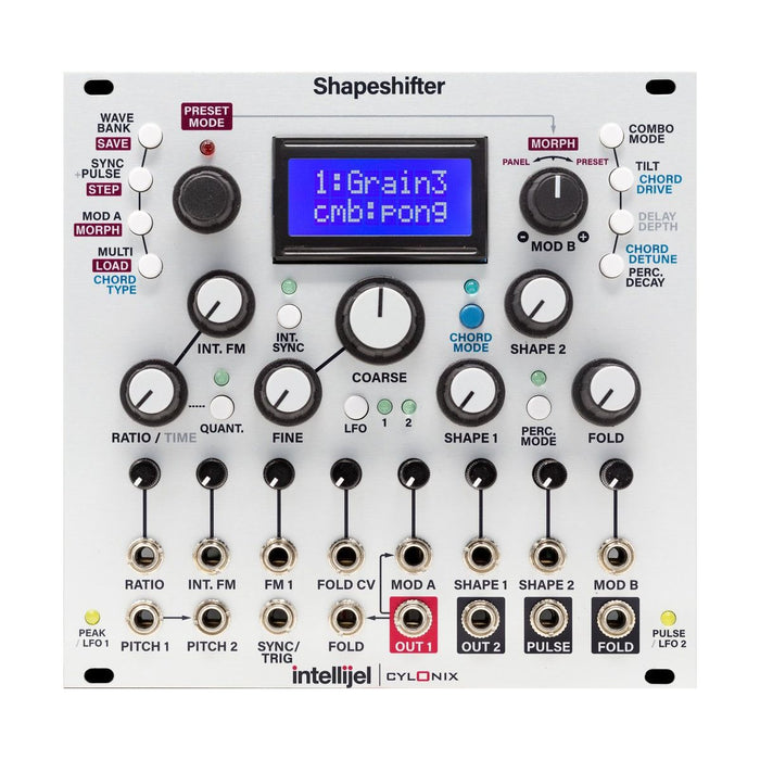
Interface
Explanation of each part is displayed by mouse over
Firmware 2.0
Changes due to a major firmware upgrade include the following:
-Chord type can now be controlled by MOD B (select chord with * in chord selection)
-Oscillator 1 and 2 wavetable banks can now be controlled with MOD B.
-Oscillator 1 and 2 can have separate SYNC mode, both can use 1 shot and hold mode
-Pressing the INT. SYNC button twice will lower the sync by one octave.
-Press the QUANT button twice and the PITCH2 input will become the external clock input, and oscillator-2 will synchronize to it. RATIO is clock division and double speed
-8 more modes for PULSE output
-A new mode has been added to the PRESET STEP menu to randomize presets for each step.
-The number of presets has been increased to 100 and all presets will be remembered even after power off
MEASUREMENTS
Detailed functions are accessed from the buttons around the LCD.
Click to expand each section.
COMBO MODE Button: Waveform Combinations
The output of output 1 is processed by a combination based on the sound of the oscillator (by digitally performing wave shaping such as an analog logic circuit), and becomes a signal that has passed through the delay. The following options are available for the combination processing (Select with Combo Mode Button). Some combination processing may be effective when performed with INT.Sync.
cmb: osc1 The sound of oscillator 1 is output as is.
cmb: ring Outputs a signal obtained by ring-modulating oscillators 1 and 2.
cmb: min Of the signals of oscillators 1 and 2, the signal with the lower voltage is always output.
cmb: pong Oscillator 1 and 2 signals. When Oscillator 1 has a positive voltage, the signal of Oscillator 1 is output. When Oscillator 2 has a negative voltage, the signal of Oscillator 2 is output. holds.
Since cmb: inlv is digital, both signals of oscillators 1 and 2 can be specified by bits, but these bit representations are specifically extracted and combined to generate a signal.
cmb: and Outputs by performing an AND operation using the bit information representing the signals of the two oscillators.
cmb: xor similarly, XOR operation (exclusive OR) is performed on the bit information of two signals and output.
cmb: gLcH Generates and outputs noisy and glitchy signals from oscillators 1 and 2 through complex calculations.
This is the waveform when trying each combination by setting oscillator 2 to 16 times the frequency of oscillator 1 with the Quant button ON.
SYNC / PULSE / STEP Button: Oscillator Sync Mode
Sync occurs when the Sync input signal exceeds 0.2V. If nothing is patched to the Sync input, it will be INT.Sync, which occurs when the signal of oscillator 1 crosses zero.
HardSync: This is the most common oscillator sync, where the phase is returned to 0 by the sync.
SoftSync: The phase that is returned to 0 by sync is the same as HardSync, but only when the oscillator phase is the first quarter (0-90 degrees).
RevSync: An oscillator sync in which the waveform direction is reversed at the sync timing. It is smoother than normal HardSync, etc., and is especially suitable for bass etc. in case of INT.Sync.
HoldSync: When a sync occurs, the signal keeps its value and the waveform starts running again at the next sync.
BumpSync: When sync occurs, oscillator 1 advances the phase by 90 degrees, and oscillator 2 advances the phase by 45 degrees.
2 = 1 Sync: This is the same sync as HardSync, but in addition to this, only the oscillator 2 is synced once again when the values of the two signals become the same.
1 = 2 Sync: 2 = 1 Sync mode where oscillators 1 and 2 of Sync are exchanged.
Sync Of: Do not sync. This has the effect of preventing glitches from appearing when stepping through the presets using the Sync input. Select this when you do not want to align the phases of the eight waveforms in code mode.
The state of each sink is as shown in the figure below. Oscillator 1/2 is a sine wave, and the yellow arrow indicates the point where sync occurs.
SYNC / PULSE / STEP Button: Pulse Source Modes
The PULSE output always outputs either 0V or 5V.
+ o1: In this mode, if the signal of oscillator 1 is greater than 0V, a value of 5V is output from the Pulse output, otherwise it is 0V.
EOC: In this mode, the signal goes to 5V at the end of the oscillator cycle. Since the oscillator cycle is usually continuous, it is always 5 V, but in percussion mode, it changes from 0 V to 5 V at the moment the percussion sound ends, so the timing of the percussion sound and other sounds is related.
+ o2: This mode is the oscillator 2 version of + o1.
-o2: In this mode, the value of 5V is output from the Pulse output when the signal of Oscillator 2 is less than 0V, otherwise it is 0V.
OR: In this mode, 5V is output when the voltage of either oscillator 1 or 2 is greater than 0V, and 0V otherwise.
AND: In this mode, 5V is output when the voltage of both oscillators 1 and 2 is greater than 0V, and 0V otherwise.
XOR: In this mode, the Pulse output outputs 0V when the output of oscillators 1 and 2 are both less than 0 or both are greater than 0, and outputs 5V when the output voltages of oscillators 1 and 2 have different signs.
gLcH: In this mode, 5V / 0V switching that reflects the sign of the output mode combination mode gLcH signal is performed. This can be selected even when gLcH is not selected for the combination mode. It's also handy for making noisy, glitchy triggers.
MOD A / MORPH Button: Mod A Destinations
The MOD A input is converted to a 98KHz digital signal and used for modulation. The MOD A input is AC coupled and does not respond to slowly changing CV (DC signal). Press the MOD A / MORPH button and use the rotary encoder to specify where to modulate the MOD A signal.
Phase2-Modulates the phase of oscillator 2.
Combo 2-In this mode, the signal of MOD A will take the place of oscillator 2 in the combination processing. Select this mode if you want to perform modulation (such as ring modulation) that is performed in combination processing, and select the combination. processing option with the COMBO button.
Shape 2-This mode modulates the oscillator 2 wavetable with the MOD A signal. Since the progress of the phase is also controlled by the MOD A signal, the PITCH 2 and RATIO signals are no longer effective, the pitch is controlled by the MOD A signal, and when the sawtooth wave is applied to MOD A, the original waveform will be reproduced.
Voc MOD-In this mode, the MOD A signal64-band vocoderVocoder processing allows you to map the spectrum of the modulation source (MOD A input signal) to the carrier signal, creating vocoder-specific robotic vocal. sounds and singing chords. The vocoder is effective when the carrier signal has many overtones like a sawtooth wave or a pulse wave.
Phase1-Modulates the phase of oscillator 1.
Combo 1-In this mode, the MOD A signal takes the place of oscillator 1 in the combination processing. with the COMBO button.
Shape 1-Oscillator 1 version of Shape 2. When oscillator 1 is in chord mode, modulation is applied only to the root note.
Voc CARR-MOD A signal is used as a vocoder carrier.
CHORD TYPE / MULTI / LOAD Button: Chord Mode
When Chord mode is activated by pressing the Chord mode button, Oscillator 1 becomes eight separate oscillators, and all oscillators can output the same waveform at different frequencies.
The detune amount can be set by pressing the DETUNE / DECAY button and turning the rotary encoder. When the detune amount is the same value, the detune may be smaller at high frequencies in terms of hearing. The detune amount can also be modulated from The MOD B input. Press the DETUNE / DECAY button twice to set. Also, tuning the codeSelectable between just intonation and equal temperamentis. Press Chord Type / Multi / Load button in chord mode and set using the rotary encoder.
When code mode is activated, the top line of the LCD display will show the currently selected code type. The chord type can be set by turning the encoder. 64 code types are selectable. The table below shows the pitch of the oscillator when displaying each chord type in semitone units. 0 corresponds to the scale of the root.
How to load the wavetable depends on the MULTI setting. In MULTI mode, you can create a more complicated waveform by connecting multiple 512 sample waveforms that are lined up on the wavetable. The mode can be selected from 1 waveform (default 512 samples) operation, 2 waveforms connecting 1024 waveforms for a total of 2 samples for wavetable operation, 4 waveform operations (2048 samples) and 8 waveform operations (4096 samples). is.
Sample waveform for each MULTI setting. Of the original 512 samples, this is the case when connecting the eight vertically displayed on the left side to make a sample.
The multi settings for oscillators 1/2 can be set individually by pressing the CHORD TYPE / MULTI / LOAD button and turning the rotary encoder.
TILT / DRIVE Button: Tilt Function
The Tilt function is to modulate the phase of oscillator 1 with oscillator 1 itself. This creates a feedback effect that tilts the waveform, but strong effects can distort or even create chaotic sounds. Tilt level is determined by pressing the Tilt button and then using the encoder and MOD B knob.
TILT / DRIVE Button: Drive Function
The Drive function is active only in code mode. You can set the gain between 1-3 and then go through the process of clipping loud sounds. In code mode, the volume may decrease depending on how the waveforms overlap, so use the Drive function to make adjustments. Increasing the gain adds saturation warmth to the sound. Adjustments and modulation settings are made by pressing the Tilt / Drive button in chord mode and using the encoder and MOD B knob.
DELAY Button: Delay Function
The combined signal is passed through a simple comb resonator / delay. It works as a resonator that oscillates when the delay time is short, and as an echo when the delay time is long. The DELAY parameter sets the amount of delay feedback and controls wet / dry at the same time. When the DELAY parameter is maximum, the echo will freeze, soOverdub and loop effectsIt can also be used as Adjustments and modulation settings are made by pressing the DELAY button and using the encoder and MOD B knob.
Delay time is not DELAY knob,Oscillator 2 cycleWill be. If you press the QUANT button and perform an echo while keeping the frequency ratio of oscillator 2 to that of oscillator 1, it will also be a resonator that synchronizes the pitch, and you can also use the sync of oscillator 2 to sync the echo time.
PERC MODE Button: Percussion Mode
Press the PERC. MODE button to switch the percussion mode. In percussion mode, the signal that has passed the combination process passes through the VCA with a snappy exponential envelope. Triggering is done by inputting a pulse signal to the SYNC input. The attack time is very short (1ms or less), and the decay decays according to the value set by the DECAY TIME parameter. You can adjust the decay time by pressing the DETUNE / DECAY button in percussion mode. To set the control by MOD B, press the DETUNE / DECAY button again.
When the PERC MODE button is pressed twiceGate modeThen, in this mode, when the gate signal entered in the SYNC input is ON, the sound is kept up to the maximum, and when the gate is turned off, the dikei begins.
Wave Folder
SHAPESHIFTER has a completely javax wave folder built into it.This wave folderuFold IIIs based on the wave folder circuit.An output of one jack is routed internally when none of the input jack into the wave folder has been stabbed.This mechanism also allows you to use the wave folder only for processes that are external to the sound.
The function of the wave folder is to wrap the input waveform and to increase the double.The amount of wrapping is determined by the FOLD knob and FOLD CV.When the amount of FOLD is small, it acts like a simple amp, but increases the FOLD, and wrapping occurs when the signal level is over there.
The appearance of the waveform when the Fold control was raised.
PRESET MODE Encoder: Preset Mode
The Shapeshifter has 64 memory slots that store the parameter setting (preset). 64 presets are available to be saved by the user, but only 12 preset slots are powered on off and not fading.It is good for 52 temporary memory to be used for preset sketches and preset steps.
Users have access to the preset mode to perform preset memory operations with the left encoder push.Indicates that the LEDs on the rotary encoder are in preset mode when the LEDs are red and glowing.When you push the encoder again, you are returned to normal mode.
and when you enter the preset mode, the buttons on the left side of the coder change the role, and the presetSAVE, STEP, MORPH, LOADand function as a means of setting up the function.
First, when you enter the preset mode, the LCD display shows the currently selected preset.If this is 1 through 12, it will be a preset that is still saved with the power off.The preset that you select can be changed by turning the encoder around (you can save or load it with the Save button or the Load button).
SAVE:
When you are in preset mode, the current parameter settings can be saved in the preset memory lease you are selecting.To do this, first cause the current preset number to be displayed on the LCD display (when in STEP / MORPH mode, press the WAVE BANK button or the CHORDE TYPE button). Then click the encoder to select the memory that you want to save, and then press the save button.So, "Save" on the LCD display? NO "causes the display to be" YES "to the right of the encoder and" YES "to save the encoder, and save it.If you don't want to save, press the encoder again .-
LOAD:
Pressing the LOAD button while the LCD display shows the preset number loads the settings for the currently selected preset. Right after the preset was loaded, the control state of the knobSoft pickupIt is in the state and does not change until the knob passes through the value of the preset's settings.Designed in this way, there is a merit that when a preset is loaded, the exact same state will be loaded, regardless of the position of The knob, regardless of the knob position (the pitch knob is a soft pickup response). Then, when you leave the preset mode, the soft pickup state will be removed, and all parameters will reflect the current knob position (hard pick up) ..
MORPH:
In the Shapeshifter, you can progressively gradually shift between the current panel settings and the settings of the preset currently selected. To do this, press the MOD A / MORPH button in preset mode.In the LCD display, "Morph NN" (NN is The preset number currently selected) and "PnL-> Pst" (or "Pnl <-PsT"). The characters are displayed. The preset currently being selected can be modified by turning the rotary encoder. The actual sound will be blended and printed With the current panel setting and the preset setting. The blend balance is controlled by the MOD B controller on the right side of the display and the MOD B input.When MOD B is left-to-left, the panel setting only sounds like a p-reset setting at the right, and the right is the only sound.
There are two exceptions to this blend. The tone of the panel setting is always printed in INT.Sync mode and Perc mode, and the preset tone is not effective.
STEP: STEP:
Shapeshifter also has a STEP mode in which the presets are progresses at the time the SYNC input is triggered on the trigger.To do this, press the SYNC / PULSE / STEP button in Preset mode. A step can be stepping within the range of the first and last presets specified by the user.There are seven different settings for step progress in step mode.
Fwd: NN If you press the SYNC / PULSE / STEP button again, the step is actually progressing.After each trigger on a SYNC input, move on to the next highest number preset. The LCD display shows the display of "Fwd * NN", and * indicates that the stapping is currently in progress. To stop stapping, press the SYNC / PULSE / STEP button again.
Rev: NN The same is the same as Fwd except that the preset number steps in the direction in which it is reduced.
Fw / Rv: NN In this mode, the preset number is on the Rev after the preset number has been increased by Fwd, and the preset number desps to repeat the preset number and then repeat it.
Rand: Randomly stapling the NN preset.
MOD B:NN In this mode, the presets chosen by the trigger are specified in the MOD B knob and MOD B controls.It is useful for fine-grained sequences of presets, for example.
Begin: NN When selected, when the SYNC / PULSE / STEP button is pressed, the LCD display is switched to "Begin?" NN ", You can then turn the encoder to specify the first preset number of the stepping, and then press the SYNC / PULSE / STEP button again when the desired number is desired.
End: NN You can specify a preset number at the end of a step in a manner similar to the Begin setting.
Div:N Specifies the number of pulses (1 to 8) that repeat the same preset in the same manner as the Begin setting.