MUSICAL FEATURES
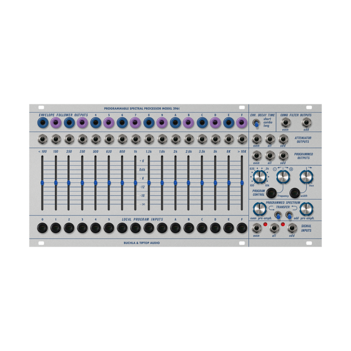
PROGRAMMABLE SPECTRAL PROCESSOR is an elaborate filter bank with various outputs and special features.The most distinctive feature is the 16-band bandpass filter. Each of the 16 bands is labeled with a hexadecimal number from 0 to F at the top and bottom of the module, and the center frequency for each band is labeled above each slider.
HOW TO USE
Interface
The explanation of each part is displayed by mouse over
Attenuator Outputs
The three signal input jacks on the lower right side of the module allow you to select the 3 even-numbered bands, all 8 bands, or 16 odd-numbered bands to input signals.on the right side of the moduleAttenuator Outputsalso provides three signal outputs: 'even', 'odd', or 'all'.If you patch a signal to the 'All' input and take the signal from the 'All' Attenuator output, the module simply becomes a filter bank controlled by sliders.If you set the slider to its lowest minimum value, the signal in that band will be completely cut off.
The 16 output jacks located directly above each slider output the sound that has passed through each bandpass filter at 0dB.These outputs are not affected by slider position.The 'Comb Filter' output in the upper left part of the module is also an output with a 0dB setting that is unaffected by the slider position, dividing the signal into all odd-numbered bands or all even-numbered bands.
Control Voltage Outputs
The 16 CV outputs labeled 'Envelope Outputs' are for each frequency band.Envelope followerThis is the output.In other words, the voltages these outputs produce represent the amplitude of the signal in each band.The decay time of these envelope outputs can be set to 'long', 'combo', or 'short' using the switch at the top right of the module.These outputs are not affected by slider position.
Programmed Outputs
The Spectral Processor mixes several band components centered on a certain frequency and can be output from the Programmed Output.Set the center frequency using Frequency in the Program Control section.Width controls the bandwidth of the mix.
Note that as the bandwidth narrows, gaps appear between bands, and at extreme settings bands disappear completely and no signal passes through.When set to maximum, each band is wide enough to encompass the entire frequency spectrum, rendering the Frequency control ineffective. Width parameter can also be controlled by voltage. 'Local Program Inputs' provide voltage control of the signal level for each frequency band.
Spectral Bias
The pair of knobs and switches located in the 'Programmed Spectrum Transfer' section arePseudo vocoder functionWe provideWhen the left switch is turned on, each Even envelope follower output is patched to the adjacent Odd CV input.This analyzes the signal present on the Even input and replicates its frequency spectrum into the Odd band. If the signal sent to the Odd input has a sufficiently wide frequency spectrum, the even outputs of the Programmed Outputs will be tonally matched to the Even signal.The switch on the right operates with a similar function in the Odd to Even direction.This is not a strict vocoding because the bands for Even and Odd are different, but you can get a similar effect by moving to the next band.
When analyzing a microphone signal, it is possible to use the harmonic-rich signal from the oscillator to replicate the vowels of the voice (vocoder patch).For this to work optimally, the input signal requires special equalization, and this is the role of the two knobs next to the switch.Turning the knob to the right and increasing the value boosts the high frequencies of even and odd input signals, respectively.These affect both the Attenuator and Programmed outputs, so unless you are creating a 'vocoder' patch, you should lower the value.
Note that the Width and Frequency controls remain active even when these switches are used.For best results with vocoder patches, set Width and Frequency to minimum.
LEDs
The LED is driven by an envelope follower and helps to confirm that a 10Vpp signal hits a specific band of frequencies and pushes the envelope follower to its maximum CV value of 10V. When using the 'Vocoder' patch, the output signal may have low gain, but by checking the LEDs and setting the VCO to the center of the band, you can maximize the gain output.Please note that LED brightness does not indicate distortion or overdrive.