MUSICAL FEATURES
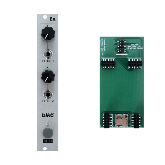
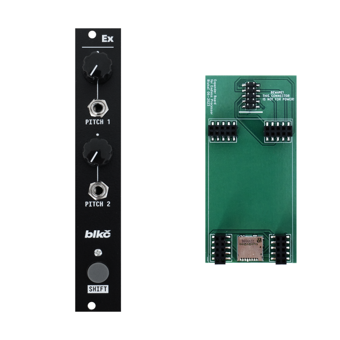
Endless ProcessorThis is a set of an expander module that adds pitch control and shift buttons to the EP, and a circuit board that is installed on the EP main board.
Pitch1,2 and 1 change the pitch of each channel. When the knob is in the middle, it's the original pitch, when it's all the way to the left it's -1 octave, and when it's all the way to the right it's +5 octave. The CV input range is -5V to +1V, with a linear response instead of XNUMXV/Oct.
You can also save and play recorded signals by operating the Shift button and the knob on the main unit.
To load a specific bank, hold Shift and align the Layer with the corresponding bank number (the LED will flash twice for each bank change), then press the CLEAR button.To save a sound to a specific bank, hold Shift and set the Layer to the corresponding bank number (the LED will flash twice for each bank change), then press the INFINITY button.
PCB mounting procedure
An additional PCB serves as a uSD card slot for storing banks and as a connection point for the expander. The additional board is installed between the two boards of the EP main body. Please follow the steps below.
- Turn off the Eurorack and remove the Endless Processor from the case.
- If you look at the back of the Endless Processor, you will see an orange DSP board, so carefully remove it.
important!Avoid touching components on the board and be careful of static electricity. Damage to components due to improper handling may cause the DSP board to malfunction or become completely inoperable and will not be covered under warranty.
- Insert the expansion PCB into the module. The orientation of the connector will guide you so you can't insert it in the wrong position.
- Insert the DSP board firmly into the connector on the back of the expansion PCB. The orientation of the connector will guide you so you can't insert it in the wrong position.

After installing the PCB. The green board with pins is the newly installed one.
- Connect the Ex module to the expansion PCB with the provided cable. Ex modules connect only to the expansion PCB and do not require additional power connections.
important!Please check the cable orientation carefully. The line below the connector indicates the orientation of the red stripe on the cable.
note!Expansion PCB or Ex moduleDo not connect to power socket.This will cause irreparable damage to the module and may damage other modules as well. Improper installation will void the warranty.