MUSICAL FEATURES
Mod Medusa is an algorithmic LFO.Four modulation channels are available, synchronized to the clock and either related to each other or independent.The timing of each channel is designed to match Euclidean-like rhythmic patterns known as trigger sequences.
Mod Medusa's waveform symmetry and shape controls offer a myriad of modulation waveforms.Assignable inputs are available for amplitude control on each channel, and you can also use ratchet or track and hold to manipulate waveform sequences.
HOW TO USE
sequencer
In a classic Euclidean sequencer Density sets the number of pulses per cycle. When Density is set to its minimum value, the sequencer is muted, increasing the number of pulses per cycle as you increase the value. Mod Medusa is not a trigger generator, so simply replace the word "trigger" with "waveform cycle" to create the modulation signal shown in Fig. 01 below.

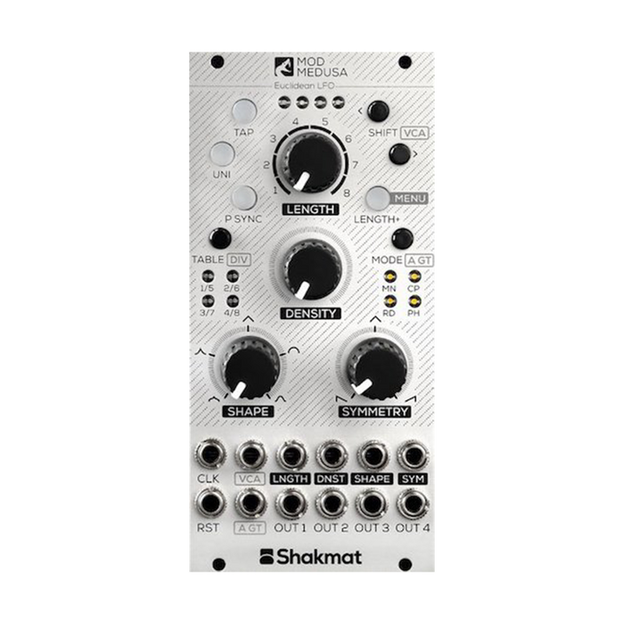
To drive the module,CLKpatch a clock signal to the input, orTAPTap the button.Like traditional Euclidean sequencers, Mod Medusa also provides Length, Density and Shift controls for the source pattern.The pattern length is set using the dedicatedLENGTHIt uses a knob and a CV input and is available in lengths from 1 to 8 steps.LENGTH+You can also access patterns from 9 to 16 steps long by pressing a button. '<'When'>', twoSHIFTYou can also use the buttons to shift the sequence forward or backward by steps, and hold the two buttons together for 2 seconds to clear all pattern shifts.At this time, the four MODE buttons flash to indicate that the shift has been reset.To reset the waveform sequence to the first step,RSTSend a trigger/gate signal to the input.
modulation waveform
Mod Medusa gives you precise control over the symmetry and shape of the modulation waveforms it generates.SYMMETRYcontinuously balances the rise and fall times of the generated waveform.SHAPEcontinuously morphs the waveform it scans and generates from sigmoidal to exponential, logarithmic, linear and sinusoidal curves.Both of these two parameters have dedicated knobs and CV inputs.
Table
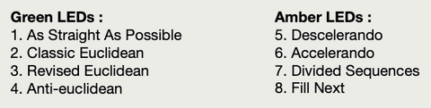
Mod Medusa is the company'sKnight's Gallopand uses a sequence table derived from the algorithm used by White Gallop.The selected table isTABLEYou can change it in the button and LED menu.
Polarity and peak synchronization
UNIYou can use the button to switch the LFO polarity between unipolar (0-5V) and bipolar (-5/+5V).The button lights up when unipolar is set.
When the Peak Sync function is off, the starting point of the waveform will be synchronized to the incoming clock signal.P-SYNCBy activating this function by pressing the button, the waveform peaks can be synchronized to the clock signal (Fig. 02).

In Correlated Mode, the polarity and peak sync changes are applied to all four channels, while in Independent Mode each channel has a different polarity and peak sync state.
2 modes
A. Correlated Outputs
Panel controls are alwaysOUT1Set each parameter of .The other 3 outputs are correlated to channel 1 and provide different modulation signals like polyrhythms.This interrelationship will change as shown in Fig. 03 based on the mode selected.

-
MN(Main): The sequences for channels 2, 3 and 4 are logically derived from the sequence for channel 1.
-
CP (Compute): チャンネル2, 3, 4のシーケンスは、チャンネル1のシーケンスに数学的に関連づけられます。例えば、'L/2 & C/2'において、チャンネル1のシーケンスが12ステップの長さで4サイクルの場合、関連するシーケンスは12/2=6ステップの長さ、4/2=2サイクルとなります。
-
RD (Random): Channels 2 and 3 randomly switch to low/high probability L/2 & C/2 patterns respectively, while channel 4's sequence is completely random.
-
PH (Phase): Each channel shifts by L/4.Under certain settings, this can produce a kind of four-quadrant modulation.
B. Independent Outputs
In Independent mode, parameters for each channel such as Length, Density, Shift, Shape, Symmetry, Table, Polarity, Peak Syncing can be set independently.FASHIONPress the button for 2 seconds and the accompanying LED will start flashing to indicate which channel is being edited.Use each control to set the channel parameters and press and hold the MODE button again for 2 seconds to exit edit mode.Note that the CV input in Independent mode affects only channel 1.
Menu
In the options menu, divide the incoming clock,A GATEassigning functions to inputs, andVCAYou can set the assignment of the channels controlled from the inputs.
Press and hold the MENU button for 2 seconds to enter the options menu,UNIとP-SYNC, the two buttons flash.To exit the menu, press and hold the MENU button again for 2 seconds.
A. Assignable Gate Input
A GATEThe input labeled can be assigned to perform one of eight different options.To toggle between these options, in the menuA GTClick the button and check the selected option by the state of the LED.

If assigned to Ratchet, the Cycle Rate is multiplied to the Ratchet Ratio when a Gate is received at the start of the LFO period.
When assigned to track and hold, the output follows the LFO cycle normally while the gate is high and holds its value when the gate is low.Using a trigger signal instead of a gate results in a sample-and-hold-like result better suited to creating stepped voltage values.
If assigned to one shot, the LFO cycle will only start when a gate is received at the start of the cycle.
TIP: By using the TAP button, you can reproduce the gate that the A GATE input receives.Pressing the MODE button and the TAP button at the same time while in the option menu toggles the function of the TAP button between tap tempo (green) and manual gate (red).
B.VCAs
While in the options menu, use the two SHIFT buttons toVCAYou can assign which channel is controlled by the input.The assigned channel is indicated by four LEDs at the top of the module.This input is unipolar (4-0V) with +5V normalized.
C.Clock Divider
Within the options menu, the TABLE button and four LEDs allow you to set the division of the incoming clock signal (4 to 1).
save the current state
Press and hold the UNI button for 2 seconds to save the current state of the module.This saves the settings for two modes, Correlated mode and Independent mode.