MUSICAL FEATURES
Pivot 2 is a compact, voltage controllable variable signal router.With the flick of a single knob, any signal can be routed to two external modules in series, parallel, or inverse series, and any combination in between.Patch wavefolders before, after or in parallel with filters, shuffle multiple delay lines, set up two-stage audio compression with precision, or create complex feedback patches with ease. It is also possible to control theIn addition to these basic signal routing uses, the Pivot 2 can also be used as a complementary pair of reciprocal linear VCAs, voltage-controlled crossfaders and panners.
- VC send/return router with analog design
- Transition seamlessly from series to parallel and inverted series effects routing
- Can also be used as a complementary VCA pair, VC crossfader and panner
- Impedance-guaranteed output with dual-color LEDs
HOW TO USE
Series → Parallel → Inverted Series Morphing using PIVOT KNOB
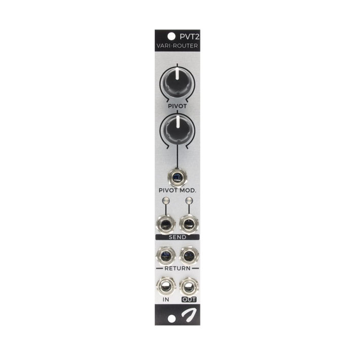
At the top of the front panel, the Pivot parameter is used to adjust signal routing throughout the module, making this control the heart of the module.
Let's say you have a processor module L between the left send and the left return, another processor module R between the right send and the right return, and patch the signal you want to process to IN.In addition, since the Send output is internally connected to the Return input, if nothing is patched from Send to Return, the Send signal will flow to Return without being processed.
Knob set to minimum (series)
Signal to IN flows only to the left SEND output. The signal from OUT comes only from the right RETURN input.A signal patched to the left RETURN input is routed to the right SEND output.Considering the processor as well, the input signal is processed in series with the processor L → R.
When the knob is set to maximum (inverted series)
In this case, the signal to IN will only be sent to the right SEND output. The signal from OUT comes only from the left RETURN input.And the signal patched to the right RETURN input is output from the left SEND.The input signal to the right RETURN is routed to the left SEND output.Considering the processor as well, the input signal is processed in series with the processor R→L.
When the knobs are set to center (parallel)
The signal going into the IN is sent to the RIGHT and LEFT SENDs equally, and the signal coming from the OUT is mixed halfway through the RIGHT and LEFT RETURN.This is called parallel routing.
When the knob is set between center and minimum (parallel & series mix)
The signal going to IN is output 100% on the left SEND and 50% on the right SEND.Left RETURN goes to both main and right SEND.The signal that passed through the right SEND→RETURN route also flows to the main and is mixed with the signal from the left RETURN.
Get any setting with a range of series, parallel and inverted series routing by adjusting the Pivot knobcan do. Pivot is capable of CV control with attenuverter.
PATCH IDEAS
Complementary VCA pair
Pivot 2 can be used as a simple linear VCA with complementary outputs, where one goes up in amplitude and the other goes down.Patch the signal to be processed to the main input. The Pivot knob and CV input are used to adjust the gain of the VCA.The right SEND output gives a standard response result with increasing gain as the value of the Pivot parameter increases.The left SEND output, on the other hand, works in the opposite direction.
Voltage controlled crossfader
To use Pivot 2 like a crossfader, connect two signals to each RETURN input and adjust their balance using the Pivos parameter.The resulting signal is available through the main output.
This crossfader does not follow standard linear laws. The two signals have unity gain when the Pivot knob is set in the center position, and are gradually attenuated as the knob is adjusted left or right.