Skip
Free domestic shipping over 15,000 yen | FREE DHL SHIPPING WORLDWIDE FOR ORDERS 50K+ yen : Details

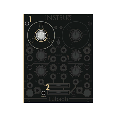
Instruo Lubadh (firmware ver1)

End of production
Full-fledged 2CH looper (firmware v1) for modular synths boasting high operability

Format: Eurorack
Width: 20HP
Depth: 42mm
Current: 250mA @ + 12V, 100mA @ -12V

Manual Pdf (English)


MUSICAL FEATURES

*This is an explanation of Lubadh firmware version 2022 before December 12.for new firmwareCurrent modulePlease see the description.

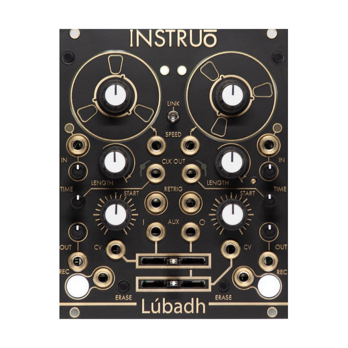
Lubadh is a full-fledged looper module for modular synths, consisting of two independent channels. By combining these two, you can instantly record (up to 2 minutes for each channel) and play, overdub, trim, scan, and pitch control. Since the output of each channel is internally connected to the input of the other channel, you can easily record and play back each other's channels, and patch them like feedback to create complex loops. In the optional delay mode, you can achieve the effect of tape delay by delaying the timing of these two channels and feeding them back (the maximum delay time is 2 seconds).

An analog input circuit that adds a little saturation is placed at the input of each channel, and depending on the gain setting, an effect similar to tape in which the sound deteriorates with each dubbing is obtained.
 

  • 2-channel looper
  • Sound recording is done at 96kHz / 24bit and internally processed at 32bit.
  • Analog input circuit affected by tape sound quality
  • LED display for easy understanding of playback speed, position, and length
  • Record up to 6 minutes for each channel
  • Tape speed control (Vari Speed) can be up to 4 times in both forward and reverse directions
  • Link switch that can switch between stereo and dual mono
  • Delay mode
  • Clock divider output
  • AUX input / output for cross-fading between channels and voltage control
  • Both recording and playback are possible with loop or one shot
  • Save / recall function
  • 2HP expander (included in the main unit) allows voltage control of all parameters
  • The reel part is a touch plate and affects the tape playback.

DEMO

HOW TO USE

Interface

 
The explanation of each part is displayed by mouse over

Record, Overdub & Erase

Lubadh is for each deck9 minutesYou can record the audio of (Firmware Ver. 1.2.f as of now).The basic recording procedure is to use an audio signalDeck1 OfInputEnter in, Deck1outputMonitor from.Input LevelSet the knob to the center (12 o'clock) position andOutput LevelThe knob is maximized clockwise.All time lap recordStart recording by pressing the button,Position / Record IndicatorBlinking indicates that Lubadh is recording.All time lap recordPress the button again to end the recording and immediately start playing the recorded audioPosition / Record IndicatorIndicates that playback is in progress with an animation that orbits the playhead.

By repeating this process, new audio is added to the existing recording.At this time, the existing overdubbed recording is always re-recorded with an amplitude setting of 0.9 in order to attenuate the old recording according to the number of steps.

To erase the audio recorded on the deckErasePress the button.

Latching & Momentary Recording

The operation when Record Gate Input receives the gate signalLatch typeMomentary typeYou can select from and set.The latch type switches the start and end of recording each time a gate or trigger signal is received.When set to the momentary type, recording is performed when the gate signal being received is high, and recording ends when the gate signal returns to low.
To switch between the two functions, hold down the Retriever / Shift buttons (2, 1) on both decks and press the Erase button (2) on the deck you want to change.By default, Record Gate Input is set to latch.

Input Monitoring Modes

Lubadh has three types of Input Monitoring Modes that can be changed according to the recording and editing process.To switch between settings, hold down the Retriever / Shift buttons (3, 1) on both decks and press the Record button (2) on the deck you want to change.

  • Input Monitoring Enabled Mode: In this default mode, the Record buttonWhiteToIlluminationTo do.Input audio monitoring is always enabled during this mode, and the signal always flows to the output with a recorded loop.
  • Armed Input Monitoring Mode: The Record button is in this modeWhite OfBlinkingIt is shown by.In this mode, input audio monitoring is enabled only when the deck is in recording standby or recording. When you press the Record button once, the button will change to blinking amber, and the deck will be ready for recording = input monitoring.If you press the Record button again in this state, recording will start with monitoring enabled.Press the Record button in succession to end the recording, disable input monitoring, and start playing the recorded loop.In addition, in the recording standby stateEraseButton operation is not clearing the loopRecording standby state OfRelease.
  • Input Monitoring Disabled Mode: Record buttonOffDuring this mode, indicated by, monitoring of the input audio signal is disabled and only the recorded audio flows to the output.

Normalization path

There is a feedback path between Lubadh's audio inputs and outputs. The output of Deck1 flows to the input of Deck2 and returns to the input of Deck2 via the output of Deck1.Such feedback paths can be used for deck-to-deck audio bounces, etc.Tape Decay modeor sending us a message onDelay modeIt is very convenient to utilize.

Time Modes

Lubadh has 3Time modeThere is, depending on the modeTimeThe role of the knob changes.To change the mode of a particular deckRetrigger / ShiftHold down button (1)All time lap recordPress the button (2).

Clock Divisions Mode: This is the default mode.The Time knob in this mode specifies the number of clock divisions per loop.Clock signal for loop1~64Can be specified between, at the timing when the clock trigger signal is generatedTime indicator WhiteToBlinkingTo do.

Tape Decay Mode: In this mode, which produces an effect similar to analog tape aging, the Time knob specifies the time until the recording deteriorates after repeated recordings.While operating in this modeTime indicator Dark blue OfBlinkingIt is shown by.

Delay Mode: The Time knob in this mode controls the signal delay time and applies analog feedback that depends on the monitoring status of the normalized signal path.While operating in this modeTime indicator Dark blue Of点灯It is shown by.

Expander

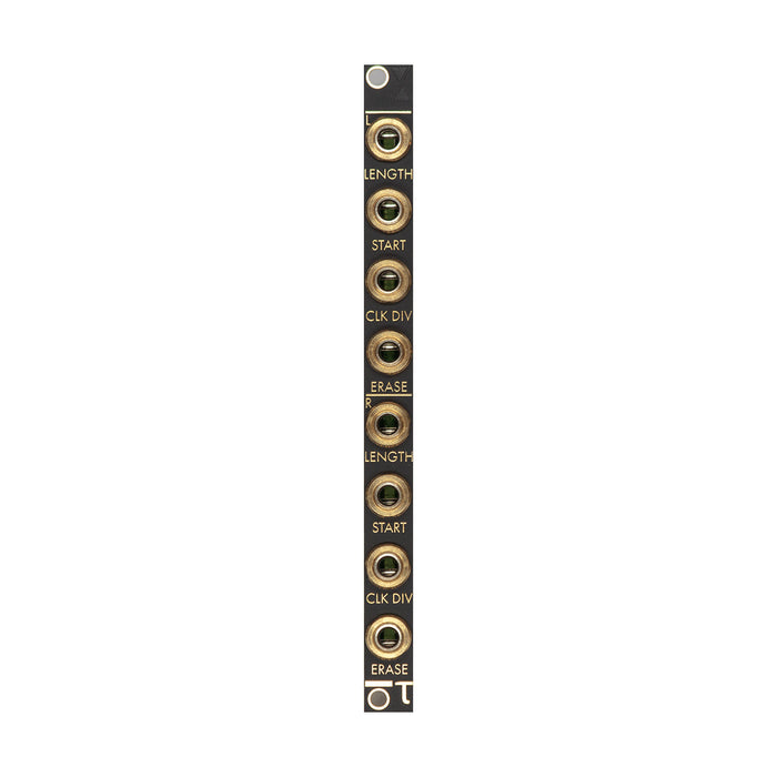
Attached 2HPCV expanderBy connecting, you can control the CV of the following parameters of each deck.

  • Length: Bipolar CV input for controlling the Length parameter of each deck. The CV is added to the knob position.The input range is +/- 5V.
  • Home: Bipolar CV input for controlling the Start parameter of each deck. The CV is added to the knob position.The input range is +/- 5V.
  • Time: Bipolar CV input for controlling the Time parameter of each deck. CV is added to the knob position.The input range is +/- 5V.
  • Erase: Clears the buffer of the corresponding deck by inputting a trigger or gate signal.


Save & Load

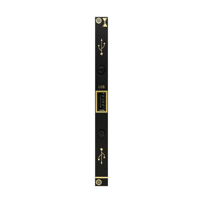
Save: To save the recording to the built-in memoryRetrigger / ShiftWith button (1)EraseHold down button (2)All time lap recordPress the button (3).The image below isDeck1Shows how to save.Also, by pressing and holding this button combination for about 2 secondsExport to USB flash driveto hold.

Load: To load a stored recording from the built-in memory to a specific deckRetrigger / ShiftHold down button (1)ErasePress the button (2).The image below isDeck1Shows how to load into.Also, by pressing and holding this button combination for about 2 secondsRead recordings from USB flash driveYou.

Even if you do not execute the button operation, the content settings automatically saved in the last session will be automatically loaded when the power is turned on.

Patch Examples

Equal Division Retrigger

Overview: Audio is recorded, looped and monitored.The clock signal generated by the loopHomeResets the loop at the position specified by the parameter.This willLengthThe loop is split evenly without the use of parameters.

  1. Input an audio signal to Input.
  2. Set the Deck1 Input Level knob to the 12 o'clock position and the Output Level knob to the maximum clockwise.
  3. Monitor the signal from Deck1 Output.
  4. Press the Record button or send a gate signal to the Record Gate Input to start recording audio.
  5. Recording ends when the maximum recordable time is reached, the Record button is pressed again, or the gate / trigger signal is input to the Record Gate Input.
  6. Set the Start knob to the desired position.
  7. Set the Time knob to loop split and patch the trigger signal output from the Clock Output to the Retrigger Input.
    Deck Bouncing

    Overview: Audio is recorded, looped, edited on Deck1 and then bounced on Deck2.

    1. Record the audio by referring to steps 1 to 5 of the Equal Division Retrigger above.
    2. Set the Speed, Start, and Length knobs to the desired positions.
    3. Make sure the Input Level knobs on both decks are at 12 o'clock and the Output Level is at maximum.
    4. Use the feedback path by monitoring from Deck2 Output.
    5. Unplug the patch cable that is input to Deck1 Input.
    6. Turn the Deck1 Time knob all the way counterclockwise and set it to generate only one trigger signal per loop.
    7. Patch the trigger signal output from the Deck1 Clock Output to the Deck2 Record Gate Input.
    8. Recording of Deck1 starts at the start of the loop of Deck2 and ends at the start of the next loop of Deck1.
    Auxiliary Feedback Delay

    Overview: Delay effect containing only wet signal

    1. Set Deck1 to Delay Mode.  
    2. Input an audio signal to the Auxiliary Input.
    3. Maximize the Deck1 Output Level clockwise.
    4. Monitor the signal from Deck1 Output.
    5. Set the Deck1 Input Level to the desired position.
    6. Patch the audio signal output from the Auxiliary Output to the Deck1 Input.
    7. Adjust the amount of feedback with the Auxiliary Output Crossfade.
    8. Adjust the Deck1 Time knob to the desired position.
    9. Apply Delay Time modulation and feedback modulation by modulating to the Deck1 Time CV input and the Auxiliary Output Crossfade CV input.
    Pitch Shifting Delay

    Overview: Pitch shifting delay effect with controllable feedback and dry / wet mix

    1. Record a sample on Deck1.
    2. Bounce a portion of Deck1's loop to Deck2.This length determines the maximum delay time.
    3. Set Deck1 to Delay Mode.
    4. Set Deck2 to Tape Decay Mode.
    5. Set Deck1 to Input Monitoring Mode.
    6. Disable Input Monitoring for Deck2.
    7. Monitor the signal from the Auxiliary Output.
    8. Set the Deck1 Output Level to maximum clockwise.
    9. Set the Deck2 Output Level to maximum clockwise.
    10. Set the Deck2 Input Level to maximum clockwise.
    11. Set the Deck1 Speed ​​knob to the original playback speed.
    12. Set the Deck2 Speed ​​knob to double speed.
    13. Adjust the Auxiliary Output Crossfade to the desired position.This mixes the original audio with the pitch-shifted audio.
    14. Control your feedback by adjusting the Deck1 Input Level to your preferred position.

    firmware Update

    The firmware update procedure is as follows.

    1. please use this form.Download the latest firmware from
    2. open source software to burn .iso and .img files,'balena Etcher'download and install.
    3. Connect the micro SD card to your computer.
    4. Launch balenaEtcher and select the firmware zip file (compressed image file) from "Select image"
    5. Press Flash!
    6. When you're done, remove the SD card, put it back into the module with the power off, and power it on without patch cables.
    7. Module loads new firmware
    Top
    x