Skip
Free domestic shipping over 15,000 yen | FREE DHL SHIPPING WORLDWIDE FOR ORDERS 50K+ yen : Details

4ms Rotating Clock Divider ( RCD )

¥28,900 (Tax excluded ¥26,273)
4HP's classic and experimental clock divider!

Format: Eurorack
Width: 4HP
Depth: 35mm
Current: 19mA @ + 12V, 4mA @ -12V, 14mA @ + 5V
(5mA @ + 33V, 12mA @ -4V when making + 12V inside RCD by jumper setting)
Manual pdf (English)

In stock. Orders made by 15:XNUMX will be shipped the same day

MUSICAL FEATURES

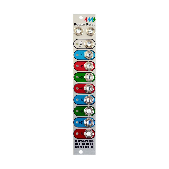
Compact Clock Divider Rotating Clock Divider (RCD) that can control CV with unique division number. Divides the input clock at various ratios and outputs the decimated clock from each output. In addition, the "Rotate" CV allows you to control the number of divisions in a unique way.

In RCD,
  • What division number of clock is output from each jack
  • Whether the output signal is a gate signal or a momentary trigger
  • Where to set the timing to output the clock even with the same number of divisions
  • Whether to reset automatically in a short cycle
It can be done by setting jumpers on the board. Or RCD Break Out Attaching allows you to control them from the panel in real time without access to jumpers. Even if you use a clock with a "partial" number of divisions, such as 5 or 7 divisions, you can create an interesting rhythm while keeping the normal bar breaks by applying the reset signal at a fine timing. It is also very useful as a rhythm experiment module.

Rotate CV
Rotate CV little by littleThe number of divisions of the clock signal increases. In many cases, the number of divisions increases by one, and when the maximum number of divisions that can be set by the jumper is reached, the number of divisions returns to 1.(The relationship between Rotate CV and the number of clock divides ismanualSee also "Rotation Tables" on page 5-6 for details. )
When the maximum number of divisions is 8 (default jumper setting), the number of divisions of adjacent outputs differs by 1, so if Rotation CV is applied little by little, the clock output from each output due to the above characteristics Moves to the next higher jack and the signal changes as the output from the top jack moves to the bottom.

MEASUREMENTS

This section describes various jumper settings on the RCD board.
 
Log Curve Curve

The 6 blue jumpers on the upper right are the jumpers set on the RCD. The image is the default setting for jumpers. In RCD Breakout, this jumper part points to the cable from RCDBO, and you can change these settings on the panel.


The image above shows the jumper on the RCD. The jumpers are numbered "7,8,3,4,5,6" from the top. The jumper is called "ON" when the two pins are connected by the jumper and "OFF" when they are not connected. The differences in the settings depending on the ON / OFF status of each jumper are as follows.
Setting Jumper 3-5

Jumper settings for Nos. 3,4,5, 3,4 and 8. The combination of numbers 3,4 and XNUMX determines the basic range of the clock signal output from the XNUMX outputs. Also, the range of the number of divisions that can be moved by Rotation CV is determined by numbers XNUMX and XNUMX (Total Rotatable Divide-by Range).

No. 5 is a jumper to set "Spread Mode". When it is On, it outputs from 8 outputs relatively evenly from a clock with a small division number to a clock with a large division number, but when it is Off, it is the maximum as shown in the table above. Only clocks that are close to the number of divisions of are output from the eight outputs.

Setting Jumper 6

6th jumper setting. When set to ON, the length will be reset according to the Divide-by Range determined by the 3,4rd and XNUMXth jumpers.

Setting Jumper 7

No. 7 jumper setting. Down-beat is a mode in which the clock of any division number starts with "ON" at the first beat. Up-beat is a mode in which the clock starts with "ON" at the last beat of each division number.

Setting Jumper 8

8th jumper setting. If you select On, the gate signal will be kept on for half the time from when the output signal is turned on until the next ON timing. When set to Off, the output signal triggers and turns on only for a very short time.

Top
x