SAMARA II is a 4-channel flexible signal processor equipped with many basic voltage processing functions such as attenuator, offset, mix, and Min / Max. Both CV and audio can be processed.
Each of the four channels has two inputs, a regular input and an inverting input, with the inverting input being inverted and mixed. After that, the signal that has passed through the attenuator is output from the OUT of each channel, but for CH4 and CH2, an offset of ± 1,3V can be optionally added before the attenuator. This allows an LFO that moves over a typical voltage range of ± 5V to be converted to a unipolar signal of 5-0V and vice versa. Offsets are prepared for channels 10 and 1, and pressing the button switches the offset ON / OFF, and long-pressing switches ± 3V.
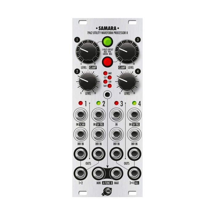
Below the four outputs of the individual channels,
FUNC outputthere is. The mix signal of CH1 and CH2 output can be taken out from 1 + 2. From 3 + 4 / ALL, extract the mix of CH1 and CH2 outputs when patched to the 3 + 4 outputs and all mix signals from the CH1 to CH2 outputs when not patched to the 1 + 4 outputs. I can.
The MIN-MAX / FUNC output is an output corresponding to the special process function that can be selected. You can cycle through the process functions by pressing the center button.
- When the LED is not lit, the default process function, MIN-MAX, is realized, and the smallest voltage value of 4 channels can be output from MIN and the largest voltage value can be output from MAX.
- MM2: In this mode, only CH1 and CH2 are processed with minimum / maximum output.
- CLAMP: In this mode, the voltage values of CH1 and CH3 are output from FUNC A and FUNC B, respectively, with the upper and lower limits of the voltage range sandwiched between CH2 and CH4. (manual(See also fig3)
- Select the voltage of CH2 to CH4 from the SCAN: FUNC A and FUNC B outputs and output. Which channel voltage is output depends on the CH1 signal.
・ CH1 3V or more: Func A = CH4, Func B = CH2
・ CH1 1V to 3V: Func A = CH3, Func B = CH4
・ CH1 -1V to 1V or more: Func A = CH2, Func B = CH3
・ CH1 -3V to -1V or more: Func A = CH3, Func B = CH2
・ CH1 -3V or less: Func A = CH4, Func B = CH4
- S & H: Acts as a dual sample and hold. When you input the signal sampled to CH1 and the signal that triggers the sample to CH2, the sampled signal is output from Func A.Similarly, the signal of sample and hold on CH3 and CH4 is output from Func B.
Switching of these process functions is done by digitally controlled routing switching, but the process itself is all realized by analog circuits.Therefore, with the sample and hold function, if the voltage is held for a long time, the voltage may gradually drop.