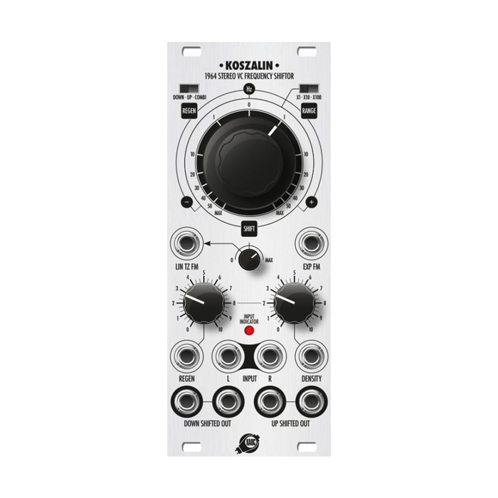
MUSICAL FEATURES
Koszalin is a 5-input 2-output, full stereo design frequency shifter that provides quasi-polynomial and linear frequency modulation up to +/- 4kHz and full stereo feedback with voltage control.You can create all sorts of atonal sounds by performing frequency shifting that linearly changes the spectrum of the signal.This is different from frequency scaling known as pitch shift, where the complex phase cancellation pattern created by frequency shift and deep feedback produces a spectacular barber pole effect. Koszalin also features a linear through-zero FM input that provides direct control over the amount of feedback, routing, and response, and facilitates frequency modulation for any stereo audio signal.
HOW TO USE
Interface
The explanation of each part is displayed by mouse over
About frequency shift
Frequency Shift, whether digital or analog, is a process that affects all spectral components of a signal by changing the frequency by an equal number of Hz for each harmonic that makes up the signal of interest.For example, if the input is a 1kHz periodic waveform, this signal usually contains 1kHz components as well as overtones such as 2kHz, 3kHz, and 4kHz.If this signal is shifted by 200Hz, the resulting signal will be 1.2kHz, 2.2kHz, 3.2kHz, 4.2kHz ...The original overtone relationship is broken.This means that the new component is not a multiple of the original frequency, and the signal will be anharmonic and aperiodic.
This is a very different effect from pitch shift, which scales the frequency by the same factor (such as accelerating the tape).For example, when the coefficient 1.2 is applied, the result is 1.2kHz, 2.4kHz, 3.6kHz, 4.8kHz .., which is 1x, 2x, 3x, 4x ... The harmonic relationship is maintained.
Technically, the frequency shift is achieved by "single side band (SSB) modulation".This is much more complicated than a simple multiplication, also known as ring modulation.This is because in simple ring modulation, the frequency added component and the frequency subtracted component are mixed.
The SSB divides the multiplied signal into a signal with a frequency shifted up and a signal with a frequency shifted down.This is the result of complex filtering, phase rotation, and quadrature modulation, which can be very complex when done in analog, but relatively easy to achieve with a DSP.
Effect of feedback
When a frequency-shifted signal is returned to the shifter's input, a portion of the signal is shifted multiple times to create a series of stepwise, continuous shifts.If the shift is slight, a very deep, resonant flanger-like comb response is created.Phase cancellation creates ripples that move in time and frequency, creating a spectacular barber pole effect.
There are also three types of feedback configurations available via the REGEN switch on the top left of the front panel.The left and center position settings allow you to select feedback created from stereo output pairs of downshifted and upshifted signals, respectively.When the switch is in the right positionCOMBIThe left channel is the signal from the shift down output, and the right channel is the signal from the shift up output. The COMBI feedback settings are useful when patching both stereo channels in series.
Negative electrode frequency (Thru Zero FM)
Suppose you have a point that makes an X rotation on the circumference in one minute.Observing this one-dimensionally, it oscillates in a sinusoidal manner at a frequency of X / 1Hz (60 minute = 1 seconds).If you slow down the circle, the frequency will decrease towards 60Hz, but if you stop the circle and change direction, the frequency will start to rise again and go towards a negative frequency value.This zero crossing is the reason why the sound of through zero FM is different from FM with positive electrode only.The frequency shift by increasing the negative value has the characteristic effect that at some point the original frequency approaches zero, exceeds it, and begins to increase again.For example, if the frequency of the input signal is 0Hz, turning the SHIFT knob counterclockwise to the -300Hz position, that is, setting it to 300 with the x10 switch enabled (using the UP SHIFTED OUT output) will correct the original frequency. , The result will be 30Hz (0-300 = 300).Beyond this point, the frequency seems to be increasing, even though the CV for the frequency is heading negative.