MUSICAL FEATURES
Nautilus is a complex delay network inspired by undersea communications and their interaction with the environment.Consisting of eight unique delay lines that can be connected and synchronized in fascinating ways, each time Nautilus activates its sonar system, the generated terrain is revealed by delays synchronized to internal or external clocks. .
A complex feedback interaction adds depth to the sound, while the associated delay line scatters sonic shards in all directions.You can further manipulate the delay line by setting the stereo receptor, sonar frequency, and aquatic substances that filter the space between Nautilus and its surroundings.
HOW TO USE
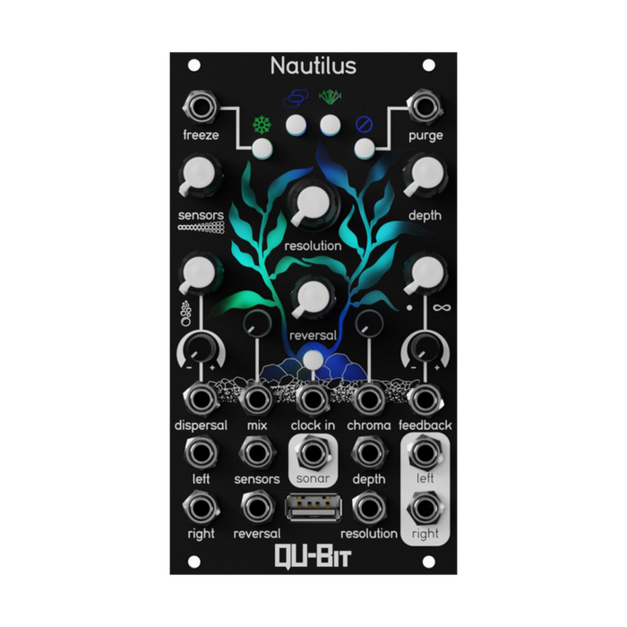
Interface
The explanation of each part is displayed by mouse over
Control details
Clock Input/Tap Tempo Button
Nautilus can run with an internal or external clock.The internal clock can be set with the tap tempo button, simply tap at any tempo and the module's internal clock will follow that tempo.
At least two taps are required to define the period of the clock.The default internal clock period at startup is always 2BPM.
For external clocks, use ' Clock In Gate Input ' to sync Nautilus to a clock source, gate signal, etc.The clock period is indicated on the 'Kelp LED' interface on the front panel.The blinking of this clock LED is also affected by the Resolution, Sensors, and Dispersal knobs (see below).
The minimum clock period is 0.25 Hz (4 seconds) and the maximum is 1 kHz (1 millisecond).
Resolution
Defines a clock speed division or multiplication value and applies that value to the delay.The division/multiplication range is the same for internal and external clocks and is as follows.

Each time a new Resolution location is selected, the Kelp LED UI will flash white to indicate that the module has changed behavior.
Sensors
Controls the number of active delay lines in the Nautilus delay network.A total of eight available delay lines, four per channel, allow you to create complex delay interactions from a single clock signal.
At the knob's minimum setting, only one delay line is active per channel (1 total), and at its maximum setting, 2 are available per channel (4 total).As you move the knob from minimum to maximum, you can hear the delay line being added to the signal path.
Each line is fairly tight at first, with rapid bursts of fire on each hit.The Kelp LED flashes white whenever a Delay Network Sensor is added or removed.
See also the next section 'Dispersal' to get the most out of the delay line's capabilities.
Dispersal
Dispersal works with Sensors to adjust the spacing between delay lines currently active in Nautilus.The amount of spacing adjusted is highly dependent on the available delay lines and Resolution parameters, and can create interesting polyrhythms, strums, or dissonances from a single signal.
When only one sensor is active, Dispersal acts as a delay fine tune, offsetting left and right delay frequencies.

Reversal
Reversal controls a delay line played backwards.This parameter is much more than a simple on/off, understanding the delay network as a whole will help you unlock its full potential as a powerful sound design tool.If one Sensor is selected, the reversal ranges are: no delay reversal, one delay reversal (left channel), both delay reversals (left and right channels).
As Nautilus uses Sensors to add delay lines, Reversal incrementally reverses each delay line.Minimum value of the knob is no inversion, maximum value inverts all delay lines.
The inversion order is 1L (left channel first delay line), 1R (right channel first delay line), 2L, 2R.
Note that all inverted delays will remain inverted until you set the knob value back below the spot in range.

Footnotes: Due to the nature of the internal algorithms that drive Nautilus' feedback network, in Shimmer and De-Shimmer modes the inverted delay line repeats once before the pitch shift.
Chroma
Much like Data Bender's Corrupt parameter, the parameter 'Chroma' is a collection of internal effects and filters that emulate underwater acoustics, marine matter, digital interference and damaged sonar receptors.
Each effect is applied individually within the feedback path.This means that if you apply an effect to a single delay line, this effect will only exist for the duration of that delay line, and the next delay line can have an entirely different effect.This allows for the layering of complex effects within the feedback path, creating vast spaces of texture from a single sound source.
Chroma effects are indicated by Kelp LEDs and are color coded.See below for details on each effect and the color of the LED that corresponds to each. The Depth parameter section explains how to use Chroma's effects.
Oceanic Absorption
Applies a 4-pole lowpass filter to the delayed signal. If Depth is the minimum value, no filtering is applied, and the higher the value, the stronger the filtering effect.Indicated by a blue Kelp LED.

White water
Applies a 4-pole highpass filter to the delayed signal. If Depth is the minimum value, no filtering is applied, and the higher the value, the stronger the filtering effect.Indicated by a green Kelp LED.

Refraction Interference
A collection of bit crushers and sample rate reduction. The Depth knob allows you to scan the setting range of the amount of change for each effect.Indicated by a purple Kelp LED.

Pulse amplification
Applies a warm, soft saturation to the delay. At minimum Depth, no saturation is applied, and higher values result in stronger saturation.Indicated by an orange Kelp LED.

Receptor malfunction
Applies wavefolder distortion to incoming audio. At the lowest Depth value, no wave folding is applied, and higher values fold the waveform more times.Indicated by a turquoise Kelp LED.

SOS
Applies heavy distortion to incoming audio. At minimum Depth, no distortion is applied, and higher values result in stronger distortion.Indicated by a red Kelp LED.

Depth
Depth is a complementary knob to the Chroma parameter, controlling the amount of the selected Chroma effect applied to the feedback path.
When Depth is the minimum value, the Chroma effect is turned off and is not applied to the buffer.The maximum value applies the maximum amount of effect to the active delay line.The only exception to this knob range is the Variable Bit Crusher, which locks the lo-fi, bit crush, and sample rate reduction settings by a random amount.
The amount of Depth is indicated by the Kelp LED, which gradually changes to each color of the Chroma effect as more Depth values are applied to the Chroma effect.

Freeze
The Freeze button locks the current delay time buffer and holds it until the button is released. The wet signal acts as a beat-repeat machine when Freeze is active, so changing the resolution of the frozen buffer can create new and interesting rhythms from the delay while remaining perfectly in sync with the clock period. .
The length of this frozen buffer is determined by both the clock signal and the period of Resolution when the buffer is frozen, with a maximum duration of 10 seconds.
The Freeze Gate input threshold is 0.4V.
Delay Modes

Press the Delay Mode button repeatedly to cycle through and choose from four unique delays.As well as mapping, communicating, and navigating the underwater world with a variety of hydroacoustic devices, Nautilus has developed a series of collaborations to re-evaluate "how we experience produced delays." Equipped with tools.
Trays
Fade Delay mode lets you seamlessly crossfade between delay times as you change the external or internal clock rate, Resolution, or Dispersal.In this mode, the LED graphic placed above the button lights blue.
Doppler
Doppler Delay Mode is a variation of Nautilus' variable speed delay time, and by changing the delay time you can get classic pitch-shifted sounds.In this mode, the LED graphic above the button lights green.
Shimmer
Shimmer Delay mode is a pitch-shifting delay set one octave above the input signal.As the shimmer delay continues to loop through the feedback path, the delay's frequency rises and gradually fades out.In this mode, the LED graphic above the button will illuminate orange.
Also, by using the Settings app and a USB drive, you can change the pitch shift amount of the delay by Shimmer in semitone steps, such as 5th or 7th.See the USB section for details.
De-Shimmer
A pitch-shifting delay set one octave below the input signal. Contrary to Shimmer mode, if you keep looping the feedback path, the delay frequency will drop and fade out gradually.In this mode, the LED graphic above the button lights purple.
Like the Shimmer, you can change the pitch shift amount of the delay in semitone steps via the Settings app and USB drive.
Feedback Modes
Repeatedly pressing the Feedback Mode button will cycle through the four different feedback paths.Different modes apply different functionality and characteristics to the delay.
Normal
Normal feedback mode provides a delay that matches the stereo characteristics of the input signal.For example, if only a signal is sent to the left channel input, the delay will also be output only to the left channel.In this mode, the LED graphic on the button will be blue.

Ping pong
Ping-pong feedback mode provides a delay that bounces back and forth between the left and right channels, depending on the initial stereo characteristics of the audio input.For example, a hard left or right input signal will also bounce back and forth in the stereo field wider than a more "narrow" input, and a mono signal will be reproduced in mono.In this mode, the LED graphic on the button will be green.

How to Ping Pong a Mono Signal: Nautilus has analog normalized inputs, so if the right channel input is not patched, the left channel input signal will be copied to the right channel.There are several options for using ping-pong mode with mono signals.
- Patch a dummy cable to the right channel input.This cuts off normalization and allows signal to flow only to the left channel.
- Patch mono audio to the right channel input.The right channel is not normalized to the left channel, so the input audio stays in the right channel even when the delay is panned left and right.
Another way to stereoize a mono signal is to use Dispersal. Dispersal offsets the left and right delay lines from each other to create interesting stereo delay patterns.
Cascade
Cascade feedback mode connects delay lines in series with each other.This means that each delay in each stereo channel feeds the next delay and finally loops back to the first delay line.
Cascade mode can be used to create extremely long delay times.Under certain settings for this mode, Nautilus can achieve a maximum delay of 80 seconds.

Adrift
Ad drift feedback mode is a combination of Ping Pong mode and Cascade mode.Each delay line feeds the next delay line on the opposite stereo channel.This creates an interesting stereo effect, like a meandering delay line, where you can't predict which sound will emerge from where.

Sensors and Cascade/Adrift modes: Sensors perform additional functions when either in cascade mode or adrift mode. When Sensors is set to its minimum value, these modes send only the first delay line of each channel to the wet signal output. Each time the Sensor value is increased and a delay line is added, the new delay line will be included in the wet signal output in Cascade and Adrift modes.
As a visual illustration, imagine a new line from ' 2L ' and ' 2R ' in the above figure connected to the respective signal output line next to it from both boxes, with a Sensors value of 2. can do.
As an example patch to see this interaction: Patch a simple, slow arpeggio to Nautilus.Set the delay mode to 'Shimmer' and the feedback mode to either 'Cascade' or 'Adrift'. Set the Resolution and Feedback values to around 9 o'clock. Set the Sensors value to 2.At this point, you can hear the pitch-shifted second delay line. Increase the Sensors value to 3.As a result, you will begin to hear a third delay line pitch-shifted two octaves above the original sound. The same is true when Sensors is set to 2.Increase the Feedback value as needed to hear additional output clearly.
Purge
Pressing this button will remove all delay lines from the wet signal, similar to purging ballast on a ship or submarine, or purging regulators during a dive.Purge is activated by a button push or a gate signal going high.
The Purge Gate input threshold is 0.4V.
Sonar
Sonar is a multifaceted signal output jack, Nautilus' collection of undersea discoveries and interpretations of the underwater world.Sonar outputs are essentially a set of algorithmically generated signals designed by various aspects of Nautilus delays.By analyzing the phases of overlapping delays and delay times, Nautilus creates an ever-evolving, stepped CV sequence. Sonar can be used to self-patch Nautilus or control other parameters in the system.
Sonar's output is also configurable using the 'Nautilus Configurator Tool' and the onboard USB drive.Configuration options include generating a ping signal based on each delay tap, an envelope follower, an additive step CV sequencer based on the aforementioned overlapping delays, or a simple clock signal copy output.See the USB section below for details.
The Sonar CV output range is from 0V to +5V. The Sonar Gate output amplitude is +5V and the gate length is 50% duty cycle.
USB/Configurator
Nautilus' USB port and accompanying USB drive are used for updating firmware, using alternate firmware, and additional configurable settings. A USB drive does not need to be inserted into Nautilus for the module to work. Any USB-A drive formatted to FAT32 will work.
Configurator
A web-based settings app that lets you easily change Nautilus USB settings' Narwhal ' to change various features and interconnections within Nautilus.Once you have the settings to your liking, click the 'generate file' button to export the 'options.json' file from the web app.
Copy the new ' options.json ' file to a USB drive and insert the drive into Nautilus.The module immediately performs an internal configuration update.Update completion is indicated by a flashing white Kelp LED.

Below are the settings currently available in the Configurator. [ ] indicates the initial setting value.More configurable settings will be added in the future.
-
Transpose Up[12]: Sets the amount of transpose in Shimmer mode in semitone units.Select a chromatic scale from 1 to 12 higher than the input signal.
-
Transpose Down[12]: Sets the transpose amount in semitone units in De-Shimmer mode.Select a chromatic scale from 1 to 12 lower than the input signal.
-
Freeze Mix Behavior[Normal]: Changes the mix response when Freeze is enabled.
-
Normal: Freeze has no forced effect on the Mix knobs.
-
Punch In: Activating Freeze when the mix is completely dry will force the signal to be completely wet.
-
Always Wet: Activating Freeze completely wets the mix.
-
Quantize Freeze[On]: Determines if the Gate input/button will freeze immediately when pressed or on the next clock pulse.
-
On: Freeze is activated on the next clock pulse.
-
Off: Freeze works instantly.
-
Clear On Mode ChangeOff: When enabled, buffers are cleared when delay and feedback modes are changed to minimize clicks.
-
Buffer Locked Freeze[On]: When enabled, all delay lines are frozen into a single locked buffer on the clock period.
-
Attenuverter 1 Target[Dispersal]: Assigns Athenuverter 1 (left) to any CV input.
-
Attenuverter 2 Target[Feedback]: Assign Athenuverter 2 (right) to any CV input.
-
Sonar Output[Stepped Voltage]:
-
Stepped Voltage: Generates an additive stepped CV sequence by analyzing overlapping delay lines (0V-5V).
-
Master Clock: Configure the Clock Input jack signal to pass through and be used at other points in the system.
-
Variable Clock: Generates a variable clock output based on the speed of Resolution.