MUSICAL FEATURES
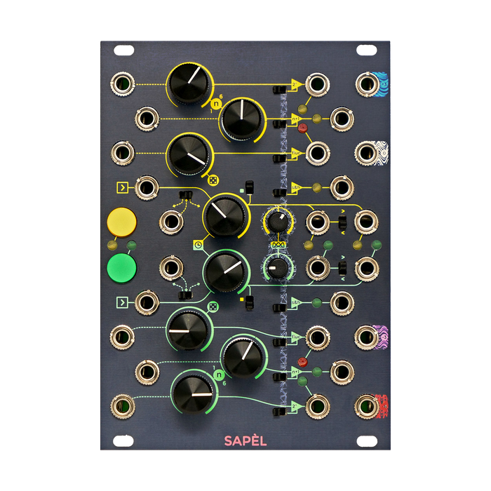
Frap Tools Sapel is a versatile random CV generator for Eurorack modular systems. The wide variety of random values generated by Sapel are sampled from analog thermal noise and add dynamics to the patch with real random generation.Random voltage / clock generationIn addition to the section4 types of audio noiseThe generation section of is also included.
HOW TO USE
The main section of the Chapel, which generates random voltages and clocks, consists of two independent channels, yellow and green.
Each channel has four sample and hold (S & H) circuits, three provide a stepwise random voltage, two are in notes, and one is not.The remaining one S & H circuit has an integrator, so the output is a voltage with continuous fluctuation.The three tiered voltage generators above are synchronized so that they can output three different values at the same time.
The yellow and green generators have two independent internal clocks that can be leveraged or temporarily overridden with an external gate or manual button.A copy of the trigger used for stepwise random value sampling, and a random trigger output are also available.The continuously changing voltage generator, on the other hand, is independent and has a control knob to define its own speed.Each aggregate is sampled from analog noise, providing true unpredictable randomness. The second section of the Sapel has four analog noise outputs, which are also used for sampling random values.
Interface
The explanation of each part is displayed by mouse over
Noise Output
This section has a unique sound quality for each color and has four analog noise outputs available for sound design.The sockets shown in each color, which are lined up at the top and bottom of the right end of the module, are arranged from top to bottom as shown below.
- Blue noise (+ 3dB / Oct spectrum)
- White noise (0dB / Oct spectrum)
- Pink noise (-3dB / Oct spectrum)
- Red noise (-6dB / Oct spectrum, also known as Brown or Brownian)
About Voltage Sampling and clock used
The two generators, yellow and green, operate independently.Each sampled three random values at the same time, one unquantized (S + H Out), One is quantized in semitones ()2 ^ n Out), One is quantized in octave units (n + 1 Out).
There are four ways to trigger the S & H circuit of each generator, combining the clocks (internal or external) of both generators with a Single / Both switch in addition to the internal clock, external clock, S & H button operation, and external S & H gate. There is also an "extra mode".
Internal Clock & Clock Modulation
The built-in clock frequency is controlled by the Clock Rate knob in the center of the module.The clock frequency can also be modulated via the Gate / CV Modulation input, which allows the accompanying switch to select two different functions.When the switch is set to the right position, the incoming CV modulates the clock frequency, and when set to the left position, any input voltage above 2V is used to activate the S & H aggregate.
External Clock
You can activate the S & H circuit by patching an external trigger to the External Clock input.If the cable is patched to this input, the internal clock will be disabled and the S & H circuit will stop triggering.This input only accepts trigger and gate signals.This is because it requires an incoming signal with a steep rising edge, such as a square wave, a pulse wave, or a sawtooth wave with a negative ramp to sample a random value.Other types of impulses such as sine and triangle waves are ignored.
Clock mix
Both the yellow and green sections of the Sapel generate their own clocks.These can be blended in a more creative way by inputting the clock of the other generator to the clock of the generator in use by setting the Single / Both switch. To enable Clock Mix, set the switch to the position labeled with the colored square mark on the other generator.This feature, which affects only the sampling section, is valid for both internal and external clocks, and all clock outputs maintain normal operation.
Manual Sampling
You can use the manual S & H button to temporarily bypass either the internal or external clock.By pressing the button, the continuous impulse is rewritten to a gate = high signal, the value is sampled, and it is held until the button is released.The accompanying LED lights up while the button is pressed. The Main Clock output continues the output of the trigger.Reference technique video (Hold)
External Gate Sampling
When the Gate / CV Modulation switch is set to the left position, the internal clock can be overwritten by patching a CV signal of 3V or higher to the Gate / CV input.This setting allows you to drive the S & H aggregate using signals other than gate / trigger.Sine waves, triangle waves, or internal Fluctuating Random can be used, but gates and square waves generally give the best results.
Clock Outputs (Main & Random)
Each time the S & H aggregate samples a value, the Main Clock output outputs a 2ms trigger.When using a stable pulse, such as an internal or external clock, this output provides a perfect copy of the clock. The Random Clock output, located to the left of the Main Clock output, allows you to add / subtract triggers in use.The switch attached to this output is in the addition mode at the upper position, and a random clock is added to all the generated clock impulses and output.When the switch is in the lower position, it is in subtraction mode, and the trigger is randomly subtracted from the one generated to trigger the S & H aggregate and output.That is, only a part of the trigger output from the Main Clock output is output.In both modes, the random clock density depends on the Global Rate of Change.Reference technique video 1, 2, 3, 4, 5, 6
Output Random Voltages value
Sapel has 3 types of stepped random (Non-Quantized 1 type and Quantized 2 types) and 1 type of continuous change random (XNUMX type of Non-Quantized type and XNUMX types of Quantized type) for each of the yellow or green generators.Fluctuating 1 type)The output is installed.The features of each output are as follows.
Non-Quantized Random Voltages
The basic stepwise random voltage generator is a sample and hold circuit that outputs the voltage value from the S & H output.This is an independent random generator, with possible voltage values ranging from 0 to 7.5V.Steplessis.If this voltage is used for pitch control of an oscillator, it will not fit in the conventional Western scale, so it will be used for more experimental music production, and often for parameters other than melody such as timbre, filter frequency, and amplitude. Used for modulation.
Quantized Random Voltages
The two graduated random voltage generators output a voltage quantized to the 2 / Oct standard.The design of these two generators follows the Buchla 1 (Source of Uncertainty), but the approach is very different, aiming for a more random voltage distribution and extremely precise quantizing that can accurately generate semitones and octaves. Designed from scratch.
The main difference from the S & H circuitry mentioned above is that, like the original 266 module, the Quantized Random generator has an n parameter that takes one of 1,2, 6, ... XNUMX. The role of the n parameter is different for each output.2 ^ n (2 to the nth root) outputIs on the 1V / Oct scaleSemitoneWill be quantized in 1 / 12V steps.In this case, the n Value knob sets an exponent of 2, which determines the number of values the circuit produces.
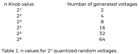
The larger the number, the larger the range of voltage (sound) generated, and the range from 1 (0V) to 64 (5.25V) is generated.This makes it possible to improve the controllability of the final output, that is, the power of expression.For example, a low n value will always produce a low note with narrow intervals, and a high value will produce a lively high note in semitones.The graph below shows the distribution of exponential notes at all n settings.

n + 1 outputIs on the 1V / Oct scaleoctaveWill be quantized in 1V steps.In this case, the n + 1 Value knob sets the number to be added to 1, which determines the number of different octaves produced by the circuit.Again, since n is any number from 1 to 6, this circuit can generate six octaves.

Even in this case, as the number increases, the range of the generated voltage (or octave) expands, and it becomes from 1 (0V) to 7 (6V).The graph below shows a linear increase in octave when the n setting is changed.

Both 2n and n + 1 support external CV control and can automate changes in the width of the output value.Reference technique video1, 2
Fluctuating Random Output
The main purpose of this section is in the range 0-7.5V.Random voltage that fluctuates continuouslyThe rate of change (or frequency) is controlled by the FRV Rate & Global Rate of Change knob.
Only this random generator is unaffected by the main clock or gate, but it does affect the clock generation itself.The secondary purpose of this section is to control the rate of change of the random clock, and the FRV Rate knob controls both the frequency of the FRV and the density of the random clock. Like the Quantized Voltage Generator, this parameter can be modulated on any CV via the accompanying CV input, and external modulation affects both the FRV frequency and the density of the random clock.Reference technique video
Probability Distribution (Stored Random Voltages)
The four random generators mentioned above are further generatedVoltage probability distributionYou can control up to.This parameter, called the Probability Distribution, is commonly set for each color via the Probability Distribution knob and can be enabled independently for each output using the four Probability Distribution switches. The PD knob sets the magnitude of the voltage generated more often.At the intermediate position, the medium voltage is output most frequently.Turning the knob to the left increases the probability of producing a lower voltage, and turning it to the right increases the probability of producing a higher voltage.
SAPEL Tamed Random Source --Overview from Frap Tools on Vimeo.