Joranalogue Step 8 is a new modular building block that offers creative functions such as a sequencer/sequential switch/counter/analog shift register through its own analog circuitry.
The advanced circuit techniques used by Step 8 avoid the problems common in analog switching/memory modules, resulting in a wideband, precision, clean signal path with low noise, distortion, and voltage droop. increase.
Analog 1:8 Voltage Tracking/Fast Sampling Register
Precise circuitry that can accurately process any signal, including pitch CV
Cycling or shifting, two sequential control modes
8 high performance "low drop" hold circuits with solo function
Integrated sequential counter with step, pause, reset and reverse inputs and step buttons
Step trigger output for easy tempo sync with additional modules
Stage CV input to directly address registers
Impedance-guaranteed per-stage analog outputs with sliders with LEDs
Scan outputs for sequencers, addressed voltage sources and waveshapers
Individual stage gate output with LED
HOW TO USE
Mode selection by switch
The operation of Step8 changes depending on the combination of switches on the top.
Cycle Mode: In this mode, the incoming voltage is attenuated according to the currently active stage's sliders and output from the corresponding Analogue Out jacks.If the input is not patched, 5V is internally connected, so a stepped voltage according to the slider like a CV sequencer is generated.Scanoutput from the jack.Solo/AllWhen the switch is set to All, the Analog Out output for each stage retains the voltage at the moment it becomes inactive. For Solo, an inactive Analogue Out goes to 0V, just like a normal sequential switch.Track/SMPThe switch sets whether or not to hold the input voltage. In the case of Track, the input voltage is output from the corresponding output as it is. In the case of SMP, the input voltage is held at the moment a stage becomes active, and the same voltage is maintained until moving to the next stage.
Shift Mode: In this mode, the input voltage is first output from stage 1, and every time a Step Trigger is received, it moves from stage 2 to 3 to 4.analog shift registerworks as
Other controls
Each of the eight stages also has an independent gate output, and the status of each stage can be checked in real time with the LEDs above the slider.The switches can be controlled sequentially with the built-in 8-step counter or directly addressed with an analog CV.
In addition, you can pause, reset, and change the direction of the counter, and by using the Scan output, you can easily and intuitively use this unit as a sequencer or address-type voltage source. Depending on the patch, it can be applied to various applications such as a divider/graphic waveshaper/multi-output analog downsampler.
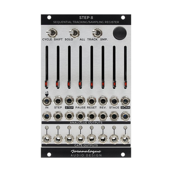
Interface
The explanation of each part is displayed by mouse over
PATCH IDEAS
Toggling Signal Mutter/Attenuator
Using the sequential characteristics of Step 8, you can switch the signal on/off.First set the module to tracking mode.Then set the odd stage sliders fully on and the even sliders fully off.Patch any signal to Input and use Scan output. A trigger signal to the Step input or pressing the manual button alternates the signal.By changing the slider value setting, you can perform attenuation instead of on/off.
clock divider
This patch example is similar to Signal Toggling above, but does not require a signal input.In this case, the Scan output alternates between 0V and 5V for each step.In other words, the step frequency is split in two. Set the sliders on/off to 2 identical pairs for 4 divisions.It is also possible to divide into 4 by setting the left half to on and the right half to off.Either clock signal or audio rate signal can be used.
Rotating shift resistor
Self-patch to permanently run ASR without annihilating the final stage.Set the module to sampling mode and patch the final analog output (8th) to Input.This causes the first stage to sample the last stage at each step, looping the analog data indefinitely.
Programmable Voltage Bank
This example patch also does not use the Input jack.Set all sliders to different positions and patch variable CVs to Stage inputs.This CV selects any of the eight programmed 8V to 0V levels and the result can be obtained from the Scan output. The Solo/All switch allows you to choose whether voltage is always available from each individual analog output, or only when a particular stage is selected.A patch that can be interpreted as a fully configurable 5-level quantizer, or voltage mapper.