Brenso is Frap Tolls' flagship oscillator that extends the concept of complex oscillators inspired by West Coast synthesis to create a wider sound palette. Equipped with a large number of circuits for interacting two triangle core oscillators to create complex tones.Of course, it is also possible to control the two oscillators completely independently.
Compared to the conventional complex oscillator, it has the following features.
Enhanced modulation routing
Ingenious sound shaping circuit design
Pingable wave folder
Oscillator sync function with a high degree of freedom
Also, it can be set for each oscillator.Through Zero Linear and Exponential FMFor each oscillator via a dedicated FM busFM DeviationCan be controlled.Furthermore, it prevents unexpected tuning troubles during live performances.Course frequency lock functionIt also answers the need for performance-oriented artists, such as the installation of. ??
HOW TO USE
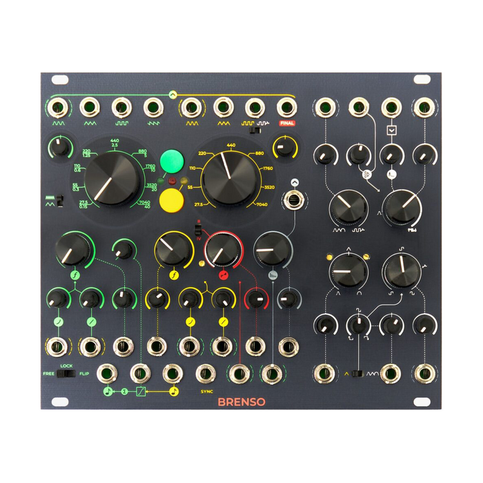
Interface
Brenso consists of a generator section (green and yellow) and a processing section (red and white) that correspond to each oscillator.The modulated yellow oscillator waveform in the processing sectionFINAL jackIs output from
Green Generator Section: Green oscillator parameters and FM bus control. FM is available in any combination of Exponential / Linear Through Zero.The sine wave of the yellow oscillator is internally connected to the modulation source jack.It is a modulation source if it is not patched.
Yellow Generator Section: Yellow oscillator parameters and FM bus control. FM is available in any combination of Exponential / Linear Through Zero.The sine wave of the green oscillator is internally wired to the modulation source jack, which is the modulation source when unpatched.
Red processing section (AM section): Ring modulation or AM of the yellow oscillator, and independent modulation bus control for them.Amplitude modulation (AM) and ring modulation (RM) can be performed to control the balance between crossfader-modulated and unmodulated signals.The sine wave of the green oscillator is internally wired to the modulation source jack, which is the modulation source when unpatched.
White processing section (Timbre section): Yellow oscillator waveshaping, And independent modulation bus controls for them. It has two parallel wave shapers that implement the PWM circuit, and after being mixed by the crossfader, it is processed by the wave folder.This wave folder has symmetry control and variable non-linear responseIt can be pinged via a dedicated clock input.The sine wave of the green oscillator is internally wired to the modulation source jack, which is the modulation source when unpatched.
?
A description of each part is displayed by mouse over.If there is an internal connection to the jack, such as the input of each modulation bus, around the jackDotted line of the corresponding source colorIs labeled, and once you get used to it, you can easily grasp the routing.
Frequency
Brenso produces sound with two individually adjustable pitch analog triangle core oscillators.These frequencies can be modulated with each other (through zero linear and exponential),sinkYou can also (Flip Sync or Lock)can.Each oscillator frequency range is labeled on the front panel27.5Hz to 7040HzThe value of.The green oscillator is a switch setting on the panelSub audio rateIn that case, the frequency range is from 0.15Hz to 40Hz.
V / Oct and Integrator
The frequency of each oscillator can be controlled from the outside by the dedicated V / Oct input.
In fact, the signal to the yellow V / oct input is actually applied to the green oscillator as well.At that time, by passing through V / oct IntegratorLag to 1V / Oct signal transmitted from yellow oscillator to green oscillatorCan be attached to the green oscillatorIt has a glide-like effect on the pitch.By maximizing the lag (full left of the knob), it is possible to prevent the V / Oct signal to yellow from being transmitted to the green oscillator, and normal operation is possible in which the pitch of each oscillator is controlled independently by each V / Oct input. is.As you turn the knob, the time it takes to reach the target voltage value becomes shorter, and when it is full to the right, the V / Oct signal of the yellow oscillator is transmitted to the green oscillator without lag.
Also, the voltage via the V / oct? Integrator is added to the green V / oct input signal.For example, you could use two oscillators in unison and control them with the same CV via the Integrator, while using the green V / oct input for an octave shift. Integration Time can be modulated by CV.
Frequency Modulation
Brenso's two oscillators are also capable of frequency modulation at audio rates.You can also use an external source to modulate the oscillator frequency, but if unpatched, the FM input of each oscillator is semi-normalized to the other sine wave.
?
FM Routing
Both Brenso oscillators act as carriers and modulators at the same time.That is, the green oscillator can modulate the yellow oscillator and the yellow oscillator can revert to the modulation of the green oscillator.This allows you to create a very complex sound with just two oscillators, with the final spectral content reaching the noise zone.
To achieve this, BRENSO has separate yellow and green oscillators.FM busEach bus has three main controls.The big knobFM DivisionWith the knob, you can also control a CV with an attenuverter.The other small knobs are the Linear TZ FM Attenuator and the Exponential FM Attenuator. The Diviation knob sets the overall amount of modulation applied to the oscillator, and the two attenuators determine the amount of FM for each linear through-zero FM and exponential FM. To get the FM effect, in addition to the Deviation control, set either the Linear TZ or the Exponential Attenuator to a value greater than 2.
When unpatched, each oscillator's linear and exponential modulation source is the sine wave of the other oscillator, as shown by the dotted line around each jack.It is also possible to disable normalization by patching another signal to the jack and use that signal.
This bus design has two major advantages, one is that each oscillator can be combined with linear and exponential FM independently, and the other is that the two buses have independent CV inputs. This makes it possible to control the amount of modulation of each oscillator with a different source, producing a clearer tone.
Sync
Brenso isn't Hard Sync, it's designed to perform different tasks.Lids"When"Flip SyncIt has two different sink circuits.Which sink circuit to use is set via the 2-position switch on the front panel for the green oscillator and through the jumper on the back of the board for the yellow oscillator.
Lock :?
The Lock circuit is used when the pitch of the oscillator (slave) is very close to an integral multiple or divisor of the frequency of the other oscillator (master).Accurate and delicate correctionIs designed to do.This is mainly used to compensate for slight tracking variability that occurs when multiple oscillators are CV controlled with the same V / oct signal.
You can lock the green oscillator to the yellow oscillator by setting the 3-position Sync switch to the Lock position.The yellow oscillator does not have internal wiring to become such a slave, but it can be locked to that waveform by setting the jumper on the back of the board to Lock and patching the external waveform to the Sync input.
Flip Sync :?Brenso's triangle core can use a sync called "Flip Sync (or Reverse Sync)".This reverses the direction of the waveform instead of forcing the slave's waveform to return to the starting point every duty cycle of the master.This technique gives a dramatic change to the slave's waveform as opposed to Lock, which makes it moreExpressive and creative purposeCan be used for.Compared to the hard sync found in typical oscillators, it produces a softer, smoother tone and allows for creative modulation without producing intense "spike" waveforms.
To enable Flip Sync on the Green Oscillator, set the Sync switch to the right position.When activated, every yellow duty cycleThe core of the green oscillator reverses the direction of its waveform.For the yellow oscillator, you can apply Flip Sync to the yellow oscillator by setting the jumper position on the back of the board to Sync, as in the case of Lock. ??
Timbre (white processing section)
All white processing sections of Brenso are designed to modulate the waveform of the yellow oscillator through a series of circuits.This section provides an overview of signal routing.
The yellow triangle wave is "triangle shaperIt is routed to a wave shaper that morphs between a sine wave and a logarithmic waveform called. Triangle Shaper can be said to be a mixer that blends three waveforms: sine wave (far left), almost pure triangular wave (center position), and logarithmic waveform.The resulting waveform is sent to one channel of the crossfader called "Source", which is the input to the wave folder in the subsequent stage.It can also be used as an input to the Pulse Shaper section.
At the beginning of the next Pulse Shaper sectioncomparatorGenerates a square wave.ComparatorExtract a square wave from the above modulated waveform,PWM (Pulse-Width Modulation) is also possible by changing the threshold of the comparator.The PWM source can also be set to a direct triangle wave from the yellow oscillator with a switch.
For that square wavePulse ShaperA CV-capable wave shaper is applied that emphasizes harmonics or low harmonics called.When the large knob on the main control is fully left, it emphasizes low frequencies.As the knob position approaches the center, the overtones in the high frequency range gradually increase.At this point, the waveform generated by the PWM circuit is reproduced almost faithfully.When the knob is above the center position, the high frequencies are gradually emphasized, with the highest amplitude at approximately 2 o'clock.From this point, the low frequency is emphasized again, but the phase is inverted, and a signal with such an inverted phase that maintains the shape of the original signal is generated up to the right full position. ..
The signal that passes through the Pulse Shaper section becomes another input to the crossfader in the Source section.
SourceThe crossfader receives signals from the Triangle Shaper and Pulse Shaper, blends them, and sends the result to the Wave Folder. SourcesEven when the position is full to the right, the signal sent to the wave shaper remains a little from the Triangle Shaper.This is a design adopted to improve the timbral characteristics of folded signals.
Wave FolderFurther processes the sound and the output is sent to other crossfaders for amplitude modulation (AM / RM) before being routed to the final output. In Wave Folder, When the waveform reaches the threshold value (both plus and minus), the waveform itself is folded instead of being clipped, and the number of folds changes depending on the folding amount.The result of these folds increases the number of overtones and produces a richer sound. The main control of Brenso's Wave Folder is the Wave Folder knob, which is labeled with six gradually thickening lines that roughly indicate the number of folds the circuit makes.The first section labeled with a dotted line simply controls the amplitude of the incoming signal from 6 to unity gain.As you turn the knob further from this point, the folds increase and reach the maximum at the full right position.Brenso's Wave Folder also adds an offset to the input waveform to change the overtone composition.SymmetryGives overtone changes with decay by control and gate signalsPingIt has an input. Ping circuit patched to inputLaunch Wave Folder with External TriggerHowever, the folding amount can be decayed. The wave folder launched by Ping opens the circuit quickly and gradually closes to the level set with the Wave Folder knob.Decay can be set with the Ping Decay knob, which is extremely fast at the full left position and longer as you turn it to the right.If you set it to the maximum value to the right, it will be difficult to understand the effect of Ping.
All of the above wave shaping techniques have been performed on the waveforms of the yellow oscillators and their application amountsModulation BusIt can be modulated (even at audio rate) by the sine wave of the green oscillator via a circuit called.The paragraphs that follow explain the modulation circuit and the role of the green oscillator and the Modulation Bus. ??
Timbre Modulation Bus
Triangle Shaper, Pulse Shaper, Source, Wavefolder, these four parameters are external CV, or "Modulation BusYou can control the voltage using the signal passed through.
Modulation BusMulti-target VCAIt is a circuit, and its input is connected from the sine wave output of the green oscillator to the CV input of the above four parameters if it is not patched.
The main large knob controls the VCA level manually, and can also be controlled externally using the CV input with a dedicated Athenu barter.The VCA is closed when the knob is fully left, and unity gain is achieved when the knob is fully right. The Modulation Bus sets the amount of signal sent to the four CV inputs, but you can also adjust the amount of modulation individually with an attenuator for each of the four circuit sections.
The main purpose of Modulation Bus is, especially when using external CVs.Simultaneously and dynamically control the amount of modulation sent to the four CV inputsIs to do.For example, set the Level knob all the way to the left to close the VCA.Then patch the envelope to the Level CV input and adjust it to any amount with the Athenu Barter.In this way, the amount of modulation sent to the four CV inputsIt is controlled by the envelope and can be scaled by the receiving attenuator.
The Modulation Bus Input, to which the sine wave of the green oscillator is internally connected, can also be patched to use an external modulation signal. The Modulation Bus Output jack can send the VCA-processed signal anywhere in the patch.
Amplitude (red processing section)
This section is a 2- or 4-quadrant linear multiplier. The 2nd quadrant is VCA (AM) and the 4th quadrant is the ring modulator (RM).The first input in this circuit is always the signal coming from the Timbre section.The second input is semi-normalized to a green sine wave by default, but you can input any signal by patching the cable to the input.
The main control is the AM / RM knob, which is basically a crossfader between the signal from the Timbre section and that amplitude-modulated signal.When the knob is fully left, the signal from the Final output exactly matches the signal from the Wave folder.Blend the amplitude-modulated signal by turning the knob to the rightAt the maximum value to the right, only the signal from the multiplier can be heard.This crossfade can also be voltage controlled with attenuverter.
This multiplier operates in 2 or 4 quadrants.Simply put, the incoming signal from the wave shaper is always bipolar, while the modulator is either unipolar (2 quadrants) or bipolar (4 quadrants). Brenso always assumes a 10Vpp signal and goes through a dedicated switchInternally scaled to perform two tasksTo do. When the AM / RM switch is in the upper position, only the positive electrode of the modulation signal is scaled to use only two quadrants.AMTo execute.Bipolar in the lower position, using 4 quadrantsRing modulationTo execute.
Details 1. About FM of Brenso
When the oscillator frequency is modulated at a sub-audio rate, it produces vibrato-like pitch fluctuations.If the signal to be modulated is an audio rate, the human ear cannot perceive fluctuations.The result of audio rate FM is a more complex sound with a timbre that is the result of the interaction of two frequencies (usually the frequency of the modulated oscillator called the "carrier" and the frequency of the modulator "modulator"). Become.The change in timbre is caused by the generation of another frequency called the "sideband," which is the sum and difference of the frequencies that are integral multiples of the carrier and modulator.If the ratio of carrier frequency to modulator frequency is an integer, such as 2: 3, the sidebands generated by FM will be harmonics that are integral multiples of the carrier frequency and modulator frequency.When this ratio is expressed as a non-integer, the sideband is anharmonic, that is, a non-integer multiple of the carrier frequency and the modulator frequency.In the latter case, this technique produces a well-known bell-like sound.
FM in the analog domain is often an approximate process because it is difficult for analog components to guarantee the exact ratio of carrier to modulator frequencies.The number and amplitude of the sidebands are proportional to the amount of modulation applied to the carriers, often referred to as "Diviation".This value defines the difference between the carrier frequency and the high or low frequencies reached when modulated.The FM index (FM index) expresses the relationship between this deviation value and the modulator frequency in Hz.For example, if the modulator frequency is 200Hz and the deviation value is 400Hz, the FM index will be 400/200 = 2.
In BRENSO, not the FM indexDivisionCan be controlled.The reason is that the unit of Diviation is Hz, and the larger the latter, the smaller the effect on the carrier frequency exponentially.This gives you a sound that is rich in low and mid range harmonics and doesn't make the highs uncomfortable. FM can be exponential or linear, depending on how the modulation is applied to the carrier signal.Linear FM modulates carriers relative to frequency.In other words, in linear FM, the carrier frequency is increased or decreased by the same Hz value according to the amount of modulation.Exponential FM modulates based on carrier frequency, that is, at intervals.A symmetric bipolar signal increases or decreases the carrier frequency at the same intervals (for example, one octave) depending on the amount of modulation.The main difference between these two technologies is that only linear FM has a carrier frequency.Side bands with equal spacing above and belowIs the point to generate.This is because the exponential modulation is asymmetric. If the waveform of A = 440Hz is modulated in the exponential form and the modulation amount is ± 1 octave, the carrier frequency is 220Hz below the original frequency and 440Hz above the original frequency? It will oscillate between 220Hz.Also, such modulation causes a shift in the center frequency.In this case, the center frequency would be 880Hz, just above 550Hz, just 220Hz, and below 330Hz.This will detune the original pitch that you can perceive.It occurs every time the carrier frequency is changed.The sideband is the sum and difference of an integral multiple of the carrier and modulator, but the difference between the carrier and modulator can be negative.These sidebands are usually inaudible because the negative frequencies are not physically present.For example, if the carrier frequency is 150Hz and the modulator frequency is 200Hz, the first few sidebands will be 350Hz and -50Hz.However, with a normal analog oscillator, oscillation stops at 0 Hz, so part of the spectrum disappears.Therefore, BrensoThrough Zero FMA technique called is introduced, and negative sidebands (sidebands located below zero) are generated with their phases inverted.As a result, there is less pitch shift than analog FM, and a richer, more natural and musical tone is achieved.
Details 2. About Brenso's Sync
Sink refers to a variety of technologies originally developed to improve and stabilize the relative frequency shifts of two or more analog oscillators.What they all have in common is that one oscillator is used as a reference to compare with the other oscillator signal, and if they are different, they are corrected, and the sink circuit also differs depending on the correction technology.
However, some sink circuits have shown that overmodulating slave oscillators adds pleasing overtones to the final sound, so these techniques sound to produce more complex timbres. -It has become widely used in synthesis.For example, Hard Sync, which is implemented in many sawtooth core oscillators.This circuit uses two oscillators called "master" and "slave" to forcibly reset the slave waveform to 2 every duty cycle of the master.Since the waveform is reset at the speed of the master, you can obtain a rich sound that changes the tone without changing the pitch by modulating the frequency of the slave.The disadvantage of this process is that every time the slave's waveform is reset and returned to the starting point, a spike-like waveform is likely to be created.
Details 3. About Lock of Brenso
The Lock system uses the master's square wave to slightly change the threshold of the slave's core, raising it when the master waveform is positive and lowering it when it is negative.As a result, the slave oscillator slowly and quickly follows the master's frequency without resetting or sudden waveform redirection.This circuit is designed to compensate for very small frequency differences and is recommended primarily when the slave pitch is within a semitone of the desired value.If the ratio between the two oscillators is not an integer, there may be some changes in the harmonic spectrum.