MUSICAL FEATURES
Expert Sleepers CVM-8 is an 8-channel CV to MIDI and CV to I2C converter. Two independent MIDI ports can be used with any MIDI device, via a 2-pin DIN, or a breakout on a 5mm TRS jack, or directly in the breakout headers of other modules in Expert Sleepers. You can connect. For modules compatible with CVM-3.5,Distinguished mk4, FH-2, ES-9(MIDI only), Disting EXIncludes (MIDI and I2C),MIDI BreakoutandTiny MIDI BreakoutAre both compatible.In addition, various basic settings can be selected with the DIP switch on the board, and complete settings and firmware updates can be performed via the browser-based configuration tool.
HOW TO USE
The CVM-8 digitizes incoming CVs to generate MIDI or I2C messages that can be used to control external devices or software.For example, you can convert hardware or software synthesizer parameters from voltage to MIdI CC for control, or convert an analog CV / Gate to MIDI notes for playing an external synthesizer on a Eurorack sequencer. .. When used with I2C, it is also possible to operate in a more passive mode in which the I2C reader references the input voltage of the CVM-8. The CVM-8 has a set of two completely independent MIDI ports and a header for I2C connectivity. One of the MIDI outputs can also drive a select bus.
Inputs
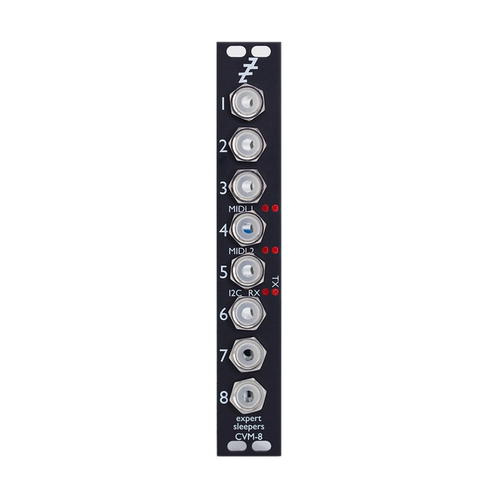
The eight analog TS input sockets on the CVM-8 can handle input voltages up to ± 8V. Patch these the signals you want to convert to MIDI.These jack sockets are illuminated, with red indicating the positive voltage and blue indicating the negative voltage.The audio signal switches between positive and negative at high speed, so it looks purple.
LEDs
The panel of CVM-8 has 6 LEDs, and 3 pairs show the communication status of MIDI 1, MIDI 2, I2C and 3 channels respectively.The left LED for each pair indicates that the module is receiving and the right LED indicates that it is transmitting.
MIDI Connections
The CVM-8 has two independent MIDI ports on the board, each consisting of traditional IN, OUT and THRU.These ports are pin headers at the top of the board and are labeled X2.

The pin number isMIDI specificationsCorresponds to the number on the 5-pin DIN socket defined in. All you need to use as a MIDI port isTiny MIDI Breakout,MIDI BreakoutOnly devices that change the pin header signal to a 5-pin DIN or TRS 3.5mm jack.Alternatively, you can connect directly to other Expert Sleepers or MIDI pin headers on compatible module boards.In this case, connect the input to the output and the output to the input.The header is a standard 0.1 "pitch header for a typical IDC cable socket, or the jumper cable that ships with the module. The THRU connection provides a buffered version of the corresponding input without the intervention of a microcontroller. Since it is output, there is no latency.
I2C Connection
CVM-8 supports I2C connectivity via a header labeled X2 on the board. The GND, SCL, and SDA lines are clearly marked on the board.Connect correctly according to the corresponding line of other I2C equipment to be used.

Wiring and disconnecting the I2C connection should be done with the module turned off. The I2C bus requires a pair of "pull-up" resistors somewhere on the bus, which the CVM-8 provides with a switch labeled SW2.The pull-up resistor is enabled when the switch is in the position of the letter PULL-UP and disabled in the opposite position.
Select Bus
The select bus is a means of communication between modules supported by several modules from various manufacturers, including Malekko Varigate 8+, Macro Machines Storage Strip, Make Noise Tempi and Rene 2. In the Expert Sleepers module, Disting mk4 and Disting EX use the select bus.
CVM-8 can only send on the select bus, not receive (Leader only).Also, there is no separate MIDI port to drive the select bus, it is driven by the output of MIDI port 2.When the select bus is connected, it always outputs the same message as MIDI port 2.To drive the select bus, the jumper labeled X5 on the board must be properly configured.The photo below shows the factory jumper settings, and the two pairs on the right will disable the select bus.To enable the select bus, set jumpers on the two pins on the left, the side with the letters SELECT BUS.Power off the module when changing the jumper position.

DIP switches
The CVM-8 board has a set of four switches labeled SW1.These are used to select the settings that will be loaded at power up. If all four switches are in the ON position, the module will be forced to boot in bootloader mode, which is used for firmware updates.Normally, you don't need this setting because you can restart the module in bootloader mode by using the Configuration Tool, but use it if you encounter problems such as the module not responding to it.
Configuration Tool
A GUI tool is available to configure CVM-8.Firmware Download PageYou can get the Config tool for your firmware version from. In addition to the standalone version for macOS and Windows, a web browser-based version is also available.It uses the Web MIDI API and will currently only work with Google's Chromium (including Chrome) based browsers. If the Config tool says'Web MIDI Status: OK', that's okay. If you see'Web MIDI Status: No MIDI Support in your browser', use a different browser.Basically, the changes you make in the tool are immediately reflected in the hardware, but any changes are not saved automatically.If you want to save your changes, save your settings in flash memory.
Tool Setup
A MIDI connection to the CVM-8 is required to use the Config tool. Both MIDI ports 1 and 2 are available and connect both MIDI in and MIDI out. At the top of the Config tool are the following controls:

Select the MIDI port of the computer connected to the module from the drop-down menu. On the right side of the MIDI port menu are the following buttons:

The'Request Firmware Version'button indicates the firmware version of CVM-8 by sending and receiving short SysEx messages.

The'Query DIP Switches' button directs you to indicate the module's DIP switch settings.

'Resynchronise' tells you to reestablish communication with the module and refresh the tool's display of the module's status.For example, it is used when the power of the module is turned off and then turned on again. 'Enter bootloader mode' is used when updating the firmware described later.Below the button is the following text box:

The box on the left is a record of the messages reported by the tool.The center box shows the last SysEx message sent by the tool, and the right box shows the last SysEx message received by the tool and, in the case of a "Message" SysEx message, the actual message as text data. increase.
Raw Inputs
Below the Log message is a section displaying raw inputs.
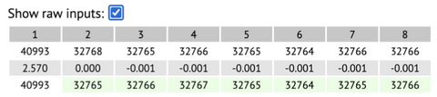
If you don't want this section to appear, uncheck the checkbox.Three values are shown for each input.The top row is the raw ADC code sent from the hardware.The middle row shows the input as a voltage, and the bottom row shows the processed ADC code used to generate MIDI and I3C messages, which is stabilized to avoid excessive noise-induced messages.A green value indicates that the module interprets the value as stable.
Statistics
Following the raw input section there is a'stats' section.

Here you can see the number of bytes received, sent, and sent via I2C on the two MIDI ports in the last second.It also shows the total number of ADC conversions performed per second.
Graph view
Check'Show Graph'to enable the graph display of each input of the module.

Inputs 1-8 are displayed in different colors in the order of red, green, blue, cyan, magenta, yellow, orange, and white, respectively.
Configuration Wizard
By using the Configuration WizardYou can quickly configure the entire module with common configuration choices, for example all inputs that generate MIDI CC, or all inputs that are used as a CV / Gate pair to generate MIDI notes. ..It is easy to use by understanding the following configuration options, there is one'Wizard'for each line.Select any setting and click the GO button.
Continuous generators
Here we set the generation of "continuous" message columns.Normally, a new message is generated each time the input voltage changes.Often these use MIDI CC or I2C controllers, but other options are available.

There are 16 generators available, and by default and Wizard, the first 8 generators are used, with a one-to-one correspondence to the eight inputs, but this association is not fixed.You can also generate 8 different CCs from a single input, if desired.Each row in the generator table is divided into four sections: Input, MIDI, I1C, and Voltage.The input section is just one control in the drop-down menu that selects the input for the module you want to use. The MIDI section begins with'Enable 1'and'Enable 1', which enable message generation on MIDI ports 16 and 2, respectively, followed by a menu of MIDI channels (4-1) and messages.Message options are CC, Program Change, Channel Pressure (aftertouch), Poly Pressure (polyphonic aftertouch), and pitch bend. For CC and Poly Pressure messages, you can select the CC number or note number of the message in the CC menu. The'Min CC'and'Max CC' menus allow you to set the minimum and maximum values for the controller sent in response to the minimum and maximum voltages (these are used for pitch bend messages that always use the maximum width). It will not be). The I2C section begins with'Enable'to enable I1C messages from this input. 'Address' sets the I2C address of the following device, and'Controller'sets the controller number. 'Min value' and'Max value' set the minimum and maximum values of the controller generated corresponding to the minimum and maximum voltages, respectively.The I1C message sent will use the '16x2' format shown below.
At the end of each line is a minimum and maximum voltage control.Voltages in this range produce controller values in the specified range.
Note generators
In this section, you can configure MIDI note on / off messages and their equivalent I2C message generation.There are a total of eight note generators that can be configured.

Each line has a MIDI section, an I2C section, and a control section that is common to both. The MIDI section has buttons for activating MIDI notes on the two MIDI ports and a dropdown for selecting the MIDI channel to use. The I2C section has an enable button and a field for entering the I2C address of the tracking device.At the beginning of the common section there are three menus for selecting the input of the module to be used as pitch, gate and velocity, all of which can also be selected as'None'. If Pitch Input is'None', the value of'Fixed Velocity'is used as the pitch. If Gate Input is'None', no new notes will be generated (a single note-off message will be generated if the note-on message was previously sent). From the 2V Note menu, you can select the MIDI note number that corresponds to the 3 volt input.Both of these polar notes follow the 0V / Oct standard. The Gate Offset menu sets a small delay between the pitch input and the gate input.By setting this value properly, the pitch CV will be established and the correct scale will be selected before the gate triggers the note. I0C messages use the 1x2 / 0x54 / 0x55 format as shown below.
Saving & Loading Configurations
Adjusted settings can be saved and loaded using flash memory, with 32 slots available.

Under'Current Configuration', the name of the current configuration is displayed.Normally, you will change the name to a descriptive name before saving the settings. The'Save Configurations' section shows the 32 slots in flash memory and the name of each configuration.Next to each name is a'Load' button to load the settings and a'Save' button to save the current settings to that slot.Also, the first 15 slots show the DIP switch settings that the slot is loaded with when power is turned on.
Settings
Unlike Configuration, which is volatile until saved, Settings are applied globally and are saved instantly.Currently, there is only one setting item, which is the I1C address of the module when operating as a follower.The initial value is 2 (50x0).

Finally, there is a'Full Reset' button at the bottom of the Config tool.This button initializes the settings and erases all saved Configurations (not a factory restore).