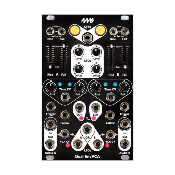
MUSICAL FEATURES
Dual EnvVCA incorporates an exponential VCA with low noise designanalog function generatorIt can also be patched to act as an LFO, slew limiter, VCA, envelope generator, trigger delay, quirky filter or oscillator.
Dual EnvVCA adds some functions to EnvVCA and makes it 2 channels, allowing flexible processing of stereo signals.
- Versatile linear envelope generator/LFO
- Low noise, low distortion, DC-coupled exponential VCA
- Full analog
- Sliders and range switches control Rise and Fall times from approximately 1.25ms (800Hz) to over 2 minutes
- Extends the time range from about 125 µs (8 kHz) to about 10 minutesTime CVジ ャ ッ ク
-
RiseとFallEquipped with a dedicated Athenuverter for each time
- Blue/red LED to indicate signal strength and polarity
-
CycleLoop Envelope with button (LFO)
- Activate Envelope single-shottriggerinput jack
- Toggle the loop state of both channelsCyclegate input jack
- Can be used for chaining or continuous eventsEOR/Fgate output jack
- without changing the volume of the VCAEnv Outcan be scaled/shiftedEnv LevelとOffsetControl
- for passing audio/CV to VCAAudio InとOctジ ャ ッ ク
-
VCA CVEach VCA can be used independently of the envelope using the inputs
- VCA CV
VCA gain is internally routed to the envelope output if there is no patch on the
- Achieve slew limiting, sustain (ASR), and unique filter effectsFollowinput jack
- Re-trig jumper setting allows re-trigger during ascending phase
HOW TO USE
Controls and input/output jacks
Cycle Button and Cycle Jack
 CycleYou can switch the cycle state of each channel by pressing the button.When cycling, the EnvVCA behaves like an LFO whose output waveform rises and falls continuously.Each button illuminates orange to indicate the module is in cycle mode.Note that envelopes that are already rising or falling will not be reset or changed by this button operation.
CycleA jack toggles the cycle state of both channels.When this button is off, the gate signal sets the button to on, cycling the channel as long as the gate is held high.When this button is on, the gate signal sets the button off, stopping any cycling while the gate is held high.
Rise/Fall slider
 RiseとFallsliders control the rise and fall times of the envelope.Moving the slider up slows down the ascent and descent parts, moving it down speeds them up.Each slider features a white LED that indicates the current stage of the envelope and output voltage.When the envelope is in the ascending stage, until the envelope reaches its maximum valueRiseThe LED on the slider will increase the brightness.Upon reaching the peak,Rise lights offFallLED lights up and dims as the envelope descends.
Rise/Fall switch
 Rise/FallA switch lets you select the overall range for each slider.There is a switch for each slider,Fast, Med, SlowYou can choose from three settings.the switchFastIn position, the envelope can operate at audio rates, making it useful for classic AM, FM and other fast modulation effects.central positionWithis designed to be used at typical musical velocities, and is useful for creating notes with common BPMs using VCAs. SlowThe setting is designed for slow modulations such as slow LFOs.
Time CV jack and Rise/Fall CV knob
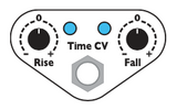 Time CVJack modulates the rise and fall times of the envelope.The signal to this jack isRiseとFall, through two knobs.These two knobs are Athenuverters,Time CVControls how much the control voltage to the jack affects the rise or fall time.Turning the Athenuverter Knob from the center to the right willTime CVA positive voltage on the jack lengthens the rise/fall times, a negative voltage shortens them.Turning the knob to the left of center will have the opposite effect,Time CVA positive voltage to the jack shortens the rise/fall times and a negative voltage lengthens them.In either direction, the farther the knob value is from the center position, the stronger the effect of the incoming CV.When the knob is set to the middle position,Time CVA signal to the jack has no effect on the rise/fall parameters.Next to each knob is an LED that indicates the intensity and polarity of the modulation. It will turn blue if the rise or fall time is extended by the CV, and red if the time is shortened.The brighter these lights, the stronger the CV effect. When the LED turns off, the envelope timeTime CVIndicates that it is not affected by Jack.If this jack is unpatched, these two Athenuverter knobs areRiseとFall Acts as a control to tweak parameters.
Env Out jack and OR jack, LED
 Env Out AとBThe jacks output the envelope for each corresponding channel.The envelope DC offset and vertical scale for each channel areLevelとOffsetdetermined by each knob in theORJack has twoEnv Outsignals and always outputs the highest voltage value between the two.LEDs near each jack indicate the strength and polarity of each envelope.The corresponding LED glows blue when the envelope is between 2V and 0V, and red when the envelope is between -10V and 10V.The brightness of each LED represents the amplitude of the output signal, so when they are off, it means the output signal is near 0V.
Level and Offset knobs
 LevelEach knobEnv OutAttenuates and inverts the envelope output of the jack.Offsetis at the center position,Levelsetting to its maximum value will output a positive envelope with a maximum peak of about 10V. Moving the Level knob to the left of its center value inverts the envelope, with an output peak of -10V at maximum counterclockwise. OffsetTurning the knob clockwise from the center position adds a positive offset to the envelope of 0V to 10V, and turning it counter-clockwise adds a negative offset of 0V to -10V.note that,LevelとOffsetNeither control has any effect on the envelope that is connected to the internal VCA.For example, with audio passing through a VCAEnv OutIf there is a patch from the jack to the modulation input of an external module,LevelとOffsetallows you to control the amount of modulation without changing the audio level.
EOR and EOF output jacks
 EORThe End of Rise jack is a channel A dedicated output that outputs a gate signal when the rise stage ends and the fall stage begins.This signal remains high during the envelope falling period and returns low when the envelope is complete.If Envelope is not working,EORThe output stays low.accompanyEOR LEDsilluminates when the output is in the high state.EOFJack (End of Fall) is a channel B dedicated output that outputs a gate signal that goes high at the end of the fall stage and stays high until the envelope begins to rise.This means that the gate signal on this jack is low only during the rising stage.accompanyEOF LEDilluminates orange when the output is in the high state.
Audio In/Audio Out and VCA CV jacks
 Audio InとOctJacks are the inputs and outputs of the VCA.VCA CVThe input is internally routed to the envelope output before passing through Level and Offset.If the envelope is stopped or at 0V,OctA jack does not generate a signal.As the envelope rises, the output signal increases until the input signal peaks in the envelope and tapers off toward silence as the envelope falls.Audio In Bis, as the panel labels indicate,Audio In Ais internally wired totherefore,Audio In BIf there is no patch inAudio In Asignal is sent to both channels.Audio In BThis connection is broken by patching to , allowing both channels to operate independently.VCA CVPatching a signal to the input breaks the internal connection between the VCA and the envelope, allowing the VCA to be used independently.VCA CVhas an input range of 0V to 5V, corresponding to about -90dB (silent) to 0dB (unity gain).
Trigger jack
 eachtriggerJack activates the envelope by receiving a minimum 2V trigger.A single trigger signal creates a complete envelope if there is no envelope already in progress.If the envelope is rising when the trigger is received, the trigger signal will be ignored (RETRIG(unless jumpers are installed).If the envelope is falling when the trigger is received, the envelope will rise from the current voltage.On the back of the module, each channel hasRETRIGI have a jumper.With this jumper installed, the envelope will instantly return to 0V and start rising whenever a trigger is received.The jumper is not factory installed as this setting produces a click on the VCA output.
Follow Jack
 FollowThe jack is both the input for the slew limiter and allows for complex envelope creation, quirky audio filtering, or use as an envelope follower.Whenever the built-in envelope is not being triggered or cycled,FollowThe envelope output rises or falls to match the voltage level to the input.However, the rise and fall times areRise/Fallis limited to each slider and amount of CV.So the envelope output isFollowIt tries to "follow" the signal present at the jack, but it can only rise/fall as fast as the envelope would rise/fall if triggered. It is called 'slew limiting' because 'slew' is the rate of change.Slew limiting isFollowandtriggerBy matching the timing of the signal at the jack, you can create complex envelopes such as ASR and ADSR.
Time span of Rise and Fall

Note that each switch setting has some effect on the operating range that can be obtained using CV.It was intentionally designed to allow full range control by an external module.
In addition, this unit is a completely analog module, and due to its nature, the maximum and minimum values of Rise and Fall are slightly different for each individual.The table above shows the basic values.
Even if each slider is in the same position, the rise and fall times are not necessarily the same.Setting them exactly the same usually requires manual adjustment. If you apply CV to create a significantly slower envelope, such as over 10 minutes, the fall time can be much slower than the rise time.Basically, the ascent time is limited to about 5 minutes, but the descent time can be set up to 20 minutes, or up to 60 minutes depending on the individual.
Creating an envelope
 Dual Env VCATo create an envelope withtriggerJack,Cyclebutton,Cyclejack, orFollowThere are four ways to use Jack.
triggerThe jack starts the envelope when a trigger signal is input.This jack responds only to rising edges, that is, when the voltage rises above 2V. Figure 1 shows that the same envelope is generated regardless of the width of the input pulse, ignoring the pulse width and falling edge.
Trigger with RETRIG jumper OFF (default)
A trigger entered while the envelope is already risingRETRIGDisabled unless a jumper is installed.If the envelope is falling when the trigger is received, the envelope will rise from the current voltage. Fig. 2 shows this, with the 5th and 7th triggers occurring during the envelope's descent to initiate a rise mid-descent.Other triggers are either invalid because the envelope is rising or starting anew because the envelope is not active.
Trigger with RETRIG jumper ON
Fig.3 isRETRIGThis shows the change in operation due to the jumper.If a jumper is installed, the incoming trigger will always reset to 0V and start rising regardless of the stage of the envelope in action.This sharp transition to 0V causes clicks when used in audio, so no jumper is installed by default.
Cycle Button/Jack
CycleA button is a simple way to activate the envelope.When this button is ON, the envelope repeats the cycle.The button is latching, so once you press it, the module will continue to output the envelope until you press it again.again when the envelope is runningCyclePressing the button will not stop the envelope immediately, it will complete the descent stage in motion before stopping.
CycleThe jack switches the cycle state of both channels by inputting the gate.CycleUsed in combination with buttons.Sending a gate to the jack while the channel's button is in the OFF state will turn the cycle ON.Similarly, if the button gates the jack when the button is ON, it cycles OFF.CycleThe button illuminates when the envelope is cycled by the button and jack combination.
In Fig.4CycleThe button is OFF in the initial state,CycleThe envelope is shown cycling while the incoming gate to the jack is high.In this case, the wider the pulse width of the gate signal, the more cycles the module will output.

Fig.5 shows the opposite situation,CycleThe button is ON by default.In this case, the envelope stops cycling during the high period of the incoming gate signal.The wider the pulse width of the gate signal, the longer the pause period between groups of envelopes.
Also notice that the first pulse in Fig. 5 does not turn off the envelope, and the triple pulse in Fig. 4 turns on only one envelope.this isCyclethat the state of the jacks and buttons only works while the envelope is off (0V)Dua Env VCAshows important aspects ofA running envelope is unaffected by any combination of gate signals and button presses, andCycle Allows cycling through jacks and buttons.
Use Follow Jacks and Gates
 Fig.6 isFollowIt shows the usage of gates in Jack.The envelope rises while the gate signal is high, and falls when the gate goes low.
The fourth gate in Fig. 6 shows how if the gate is held when the envelope reaches its maximum value, the envelope is also held until the gate is released.this isASR Envelope(Attack Sustain Release) is one of the easy ways you can create it.
In subsequent short bursts of multiple pulses,FollowIt shows how complex envelope shapes can be created using only jacks and successive gates.
In addition, FollowThe jack can also be used for signals other than gates as described in the next section.
Follow Jack Basics
The Follow jack raises/lowers the envelope to follow the incoming signal.Sending a high voltage (5V) to the jack raises the envelope, while sending a low voltage (0V) lowers it.this is the previousCreating an envelopeYou can see it in Fig.6 in the section. More complex effects can be achieved with voltages in the 0V to 5V range, such as LFOs or audio signals.
Below are two basic rules for understanding this Jack.
-
Rule 1: If the voltage to the Follow jack is higher than the envelope voltage, the envelope will rise, and if the voltage to the Follow jack is lower than the envelope voltage, the envelope will fall.
This means that the Envelope will always try to pick up the signal on the Follow jack,Followrises if the signal of is higher than itself,FollowIf the signal of is lower than itself, it will descend.This is why the term ' follow ' is used.
-
Rule 2: The envelope isRise/FallIt can only ascend/descend at the speed set by the control and CV.
this is,FollowIf the voltage on the jack suddenly rises (for example, a gate signal is applied), the envelope will try to keep up, but only as fast as the control allows.The follow circuit is called a "slew limiter" because the rate of change, or slew, is limited.
Note that the term 'envelope voltage' in Rule 1 isLevelとOffsetKnobs, andEnv OutRefers to the internal envelope voltage before being sent to the jack's output driver.The internal envelope amplitude is 5V maximum and 0V minimum, which isFollowThat's why the jack only responds to voltages between 0V and 5V.Env OutThe jack's output driver doubles the internal voltage, so an internal envelope of 5V results in an envelope of approximately 10V at the output jack.
With these two basic rules in mind, the following sections will introduce advanced uses of Follow Jack.
Sidechain (Envelope Following)
FollowJacks can be used to create an envelope that follows the envelope of the audio signal.By inverting this envelope and using it to control a VCA, you can get the effect of 'ducking' other sounds.This technology is called 'sidechain'.
A typical use is ducking other sources, such as background drones, with a kick drum.Set the kick drum sound source to channel B.Followpatch the jack,Cycleis ' off '.The switch is ' With ',RiseSlide the slider all the way down,FallStart with the slider in the middle position.LevelRaise theEnv Out Boutputs an envelope that roughly follows the kick drum envelope.RiseとFallYou can control the envelope attack and release times, or how quickly the envelope responds to the kick drum attack and release, by adjusting the .
In this example, we need to invert the envelope, soLevelcounterclockwise,Offsetto a value around 2:00.This willEnv Out Boutputs an inverted envelope that stays at about 5V and ducks with kick drum playback.Put this inverted envelope on channel A.VCA CVPatch Jack.Ducking audio, such as drone sounds, on Channel AAudio InConnect toAudio outmonitor.You can see that the volume of the drone drops when the kick drum is played.The full effect can be seen by listening to the drone and kick drum at the same time.
on channel BRiseとFallAdjusting each slider controls how quickly the envelope responds.If the slider is set too fast, the envelope will trace individual peaks of the sound waveform rather than the entire envelope, resulting in a more dense AM effect.If the slider is set too slow, there will be less change in volume when the kick drum is played.
Also, for channel BOffsetとLevelYou can also control the dynamics range of the ducking by adjusting the knob.If you want to reduce the amount of ducking, useLevelTurning the knob toward the center reduces the amplitude of the envelope.On the other hand, if the kick drum feels small,LevelBy setting the knob to its extreme counter-clockwise position, you can generate an envelope with enough amplitude to get the desired ducking effect.Offsetshould be set somewhere between 1:00 and 3:00 in most cases.Too low and the output will be too low, too high and the output will be maximum volume with very little ducking.
audio filter
FollowThe jack can also be used as a quirky low pass filter with its slew limiting properties.First, adjust the audio signal to be used so that it is within the range of 0V to 5V.Typically, a level shifter is used to add the necessary DC offset and an attenuator or similar to attenuate the audio so that it does not exceed 5V.Any signal outside this range will be clipped, resulting in severe distortion.
This adjusted audioFollowpatch the jack,Env OutPatch the jacks to any mixer or amplifier. Levelto the maximum,Offsetto the center position.Rise/FallStart by setting the sliders and switches to their fastest positions.a constant positive voltageTime CVsend it to jackRise CVとFall CVSet the knob to its minimum value.At this point, you should be able to hear an audio signal that is close to the original signal.Rise/Fall CVAdjust the knobs and sliders, orTime CVBy adjusting the CV patched to the jack to slow down the Rise and Fall times, the slew is limited and high frequencies cannot pass through, adding a filtering effect to the audio.Try adjusting either Rise or Fall alone to create a more exotic sound.It changes how high frequencies rise and fall, creating unique overtones.
wave shaper
Limiting the slew allows smooth transitions in waveforms with sharp transitions.for example,FollowIf a square wave is input to the jack,Env OutJacks produce waveforms that look like trapezoids or triangles.Rise/FallBy adjusting the sliders and switches, you can obtain an output waveform with maximum amplitude while maintaining the desired amount of wave shaping.These controls will need to be adjusted again if the frequency of the waveform changes.Time CVwith JackRise/Fall CVBy tracking the frequency with the knob, you can create a variable frequency waveshaper with some consistency.
Portamento/Glide
The output of a CV/GATE keyboard or sequencer is primarily a 'step' shaped waveform that changes from one voltage value to the next each time a note is played.The result of patching this voltage to a VCO is a sequence of notes that change from one note to the next.Creates a 'glide' from one note to the next by adding the right amount of slew to the notes.This effect is known as 'portamento' or 'glissando'.Dual Env VCALet's take this stepped waveform asFollowpatch the jack,Env OutYou can do this effect by taking the output from the jack.The amount of glide effect is controlled by the Rise and Fall times. When patching to the pitch input of the VCO,LevelとOffsetYou can adjust the tuning with each knob on the .note that,Dual Env VCAis not a module designed for precise portamento effects, so accurate tuning over a wide range is not guaranteed.
Creating ASR/ADSR Envelopes
 ASR Envelope
The ASR envelope is a trapezoidal envelope with an ascending slope (Attack), a flat high holding portion (Sustain), and a descending slope (Release).The length of this sustain stage varies with the length of the high state of the input gate, as shown in Figure 7.this istriggerpatch to jackCycleGenerate a triangular envelope using a buttonARThis is in contrast to the (Attack-Release) Envelope.
Dual Env VCAYou can use one of the channels to generate a variable width square wave and the other to create an ASR envelope.Cycle with Channel B's Cycle on and use multiple or stacked cables to route the EOF output to Channel A's output.Followwith JacktriggerPatch Jack.audio sourceAudio Inpatch the jack,Audio outMonitor Jack.
on channel ACycleis off, and the fourRise/FallSet all switches to 'Med'.Adjust the sliders so that channel A's slider is lower (faster) than channel B's.on channel BRiseとFallBy adjusting the overall tempo,RiseThe slider alone controls the length of the sustain stage.Also, for channel BEOFYou can also use your keyboard instead of Jack.keyboard gate output on channel AtriggerとFollowPatch each to the jack.If you press the keyboard quickly, you can play staccato, and if you press the keyboard long, you can play long notes.Note that the minimum (shortest) note length is always determined by Channel A's Rise and Fall parameters, regardless of how short the input gate is.EOFBesides jacks and keyboards, it is also possible to use the gate output of a sequencer with a gate length (pulse width) control.By increasing the gate length of certain notes, you can emphasize/accent them in your sequence.If your sequencer doesn't have a pulse width control, use Channel B'striggerpatch the jack,Cycleturn off the button.
 This patch changes the gate signal totriggerとFollowworks by patching both jacks.triggerThe jack ensures that the full envelope is output even with extremely short gate widths,FollowJack generates sustain.gate signaltriggerIf you patch just the jack, you won't get any sustain as the envelope will start falling when it reaches its peak.FollowThe sustain portion of the envelope is created by holding the envelope high while the gate to the jack is high.ConverselyFollowIf patched to the jack only, a short gate input will create a perfect envelope only if the Rise parameter is very fast. A gate shorter than the Rise time will result in a non-peaking envelope as shown in Fig. 6 in the previous section.the gatetriggerとFollowBy patching both jacks, you can get a perfect envelope regardless of the settings, as shown in Fig.7.Notice how the width of the pulse relates to the sustain of the envelope output. You can see that the width of the first pulse is shorter than the time it takes for the envelope to rise, not enough to produce sustain.

ADSR Envelope
ADSR is a 4 stage envelope with an added 'decay' stage after the attack stage. After peaking, the ADSR envelope decays to a sustain level below the peak level. Figure 8 shows that this sustain level and the rate at which the envelope decays can be controlled.
Dual Env VCANow let's change the gate signal toFollowYou can generate an ADSR envelope by sending it to Jack.The gate to be used should be generated by an external module such as a keyboard or sequencer that can control the pulse width.This pulse width determines the sustain length.In other words, the ADSR Envelope runs through the attack and decay segments and holds the sustain level until the gate goes low.Also, the release segment is executed at that time.
Use multiple or stacked cables to route the gate signal to channel A.triggerjack and channel BFollowPatch the jack (in the image aboveTime CVis also patched, but you can ignore it for now).Env Out Bto channel AFollowPatch Jack.of both channelsCycleturn off the button. The ADSR envelope is channel A'sEnv Outoutput from the jack.Channel A to use audioAudio In / Outuse jack.
 Switch channel A toWithand set the two sliders toNearly.2 or 3 ticks higher thanRiseis the attack time,Fallcontrol both the release and decay times respectively.Channel B is basicallyEnv OutConfigured as a follower with fast Rise/Fall times to pass input gates from Jack.The amplitude of the gate output isLevelYou can control it with a knob.This variable amplitude gate is then placed on channel A.Followsend toThis amplitude sets the sustain level, as explained below.note that,LevelThe knobs are sensitive, so this patch will only work at settings between 12:00 and 3:00.
Sending a gate will generate an envelope as shown in Fig.8.This gatetriggerA rising edge on the Gate triggers Channel A because it is patched to the jack.This causes the envelope to rise to its peak and begin its descent into the Decay stage.on channel AFollowOnce the jack level is reached, it is held during the sustain segment.FollowJack level is Channel BLevelBecause it is controlled by the knob,LevelA knob controls the sustain level.FollowWhen the jack gate goes low, the envelope will switch to channel A during the release stage.FallIt returns to zero at a speed defined by the slider and switch.
At this point, attack or rise speed (Riseslider/switch), sustain length (gate pulse width), and sustain level (Level knob) can now be controlled.However, the decay time and release time are alwaysFallIt becomes the value set by the slider/switch.
To turn this into a true ADSR envelope, use a multiplexed cable from your keyboard or sequencer gate output.Time CVPatch the input.At this time, the gate output of the keyboard or sequencer is channel A.triggerand channel BFollowMake sure it remains connected to theThis willFall CVThe knob allows you to set the decay time relative to the release time.Turning it to the left of center makes the decay time faster than the release time, and turning it to the right does the opposite.This behavior is because the decay stage occurs when the gate is high and the release stage occurs when the gate is low.the gate isTime CVSince it is patched to the jack,Fall CVThe position of the knob only affects the decay stage while the gate is high.again,FallAdjusting the sliders or switches will change both the decay and release times.
To create non-classical envelope shapes, switch Channel B toWith, and on each sliderRiseとFallAdjust to delay the time of
Offset and Level knobs
LevelとOffsetEach knob ofEnv Outof the output signal from the jackamplitudeとDC levelcontrol respectively.They have no effect on the VCA or audio signal unless the Env Out is patched to a VCA CV. Independent of the VCA,Env Outto modulate anything with and without interfering with the VCALevelとOffsetcan be used to control this modulation.
LevelThe knob controls the amplitude of the envelope.No envelope is output when the knob is in the middle position.Rotating the knob to the right of center results in the most common envelope setting, where the envelope voltage rises upwards and falls downwards.If the knob is turned left of center, the envelope will be inverted, rising downwards and falling upwards.In either direction, knob values farther from center have greater amplitude, with a maximum value of about 10V.
OffsetThe knob shifts the envelope output up or down.When the knob is in the middle position, the envelope rests at 0V, from whichLevelIt will go up to the voltage value that the knob sets (+10V, -10V, etc.).OffsetWhen the knob is turned left of center, the envelope will rest at the negative voltage.The quiescent point at maximum counterclockwise is -10V.Conversely, when turned to the right of the center position, the envelope will rest at a maximum positive voltage of +10V.
Env OutThe jack clips at approximately -10V and +10V.LevelとOffsetextreme settings of each can easily clip to give a stable output of -10V or +10V (usually not very interesting in patching).LevelとOffsetIf you are unsure how to setOffsetto the center position,LevelA good value to start with is around 3:00 or higher.
RETRIG jumper
 on the back of the moduleRETRIGThe jumper is already triggered when the envelope is in motion.Dual Env VCAchange the behavior ofThe jumper is not installed at the factory and in this state any trigger received while the envelope is rising will be ignored, and if triggered while the envelope is falling it will rise again from the current voltage.
If jumpers are installed,Dual Env VCAwill restart the envelope as soon as a trigger is received, regardless of whether the envelope is rising or falling.In this case the envelope immediately drops to 0V and then rises.This sharp transition to 0V will produce a click when used with an audio VCA section.
VCA minimum gain trim
 On the back of the module is a trimpot that adjusts the minimum VCA gain.This is normally set to prevent audio leakage when the envelope is not running, but if you set the minimum gain value too low,Dual Env VCAwill cause the gaps between notes to grow as they cycle.This means that the time between peaks in the envelope increases and the sound becomes inaudible or almost inaudible.
With the trimpot set to its fully counter-clockwise minimum, the VCA attenuation is -90dB when the envelope is not cycling.This is the maximum amount of silence between notes during the cycle, and the minimum amount of leakage.The default mid-position setting has an attenuation of -80dB.In this case, the silence between cycles of the envelope will be short and the leakage will be small.With the trimpot set to its maximum clockwise value, the attenuation at envelope stop is -30dB.This setting is useful when you want less silence between cycles, or when you don't mind a little audio leakage when not cycling.